I've successfully made the FS BMS to communicate with Cerbo GX and take over control of the system. FS engineer worked from his weekend time today to support me. Shows up in Cerbo GX as a Pylontech battery. Had to make my own cable. However, had shutdowns in my system twice on multiple alarms. BMS Showing wrong voltage at 106.4V and wrong SOC at 100%. The BMS is showing twice the correct voltage and half the correct current. Even after I disconnected the BMS cable and disabled the BMS-CAN communication and BMS battery measurement in DVCC / Cerbo GX, my charge controllers refused to charge and kept giving error 67. To solve this (i.e. revert to pre-BMS control state), I had to reset the charge controllers in VictronConnect and enter set points afresh. For the Quattro, I just uploaded a backup of the last working file in Remote VEConfigure. Everything is now normal (as before introduction of BMS connection to Cerbo GX). On Monday, after I get the solution to the wrong voltage and current measurements by the BMS, I will commission the BMS control again. An FS engineer is helping me on this.
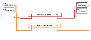
The BMS is thinking I have two groups of series connected batteries, 2P2S instead of the actual 4P batteries. Attached picture shows how the 4 nos. 10kwh FS batteries (I think they are actually 8.75kwh but good for the price and have 5 years warranty) are connected to the 48V DC (nominal) busbars.
View attachment 160007


")