diy solar

diy solar

Final LFP Charging settings with Batrium BMS?

Sorry for the delay, yesterday was a travel day :)

ah yes, completely makes sense on the generator, charge up faster to use less fuel. I was thinking at it from a charging/balancing perspective not from a fuel efficiency perspective.

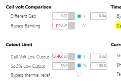
Here are my current Auto Level settings

Definitely not good autolevel settings. There is zero value in any balancing below 3.40V. It may actually be counter-productive.
1678907803226.png


Cell banding should be at or less than the Different Gap value. This is used to restrict the balancing to a smaller value than the gap, e.g., let's say you only wanted a 0.05V gap, and when that happened, you only wanted the worst 0.02V cells balanced to keep the balancers from hover-heating.
 
Definitely not good autolevel settings. There is zero value in any balancing below 3.40V. It may actually be counter-productive.

View attachment 139701


Cell banding should be at or less than the Different Gap value. This is used to restrict the balancing to a smaller value than the gap, e.g., let's say you only wanted a 0.05V gap, and when that happened, you only wanted the worst 0.02V cells balanced to keep the balancers from hover-heating.
thanks! I kinda figured it would need some work. there is a decent video on YouTube from a gentleman that talks through each of the settings but he uses other lithium cells I believe, not LFP

Settings updated, we'll see how this does.
 
Where is that page located? I just looked and didn't find it. Looked under Hardware and Control Logic.
Yeah it’s a little “hidden”
Hardware, cellmon tab, look towards the bottom left for a small text/button that says “more…”

You have to click the Edit button on the cellmon tab before making any changes to that pop up.
 
I only have an Advanced tab under Edit for Cellmon tab. I'll have to plug in as it won't allow the Advanced tab to work on WiFi.

I swear I have seen that page before, but was plugged in.
 
Now I found it. I didn't use Extra Mode, I've been just letting it run Bypass at Bulk charge. I see for the factory default under the More button it has Different Gap as 0.01V and Bypass Banding at 0.25V. Cell Low Cutout was 3.40V.

You are stating Banding should less than Gap?

I should have clarified.

In a functional system maintaining balance, it's mostly meaningless if it's larger than the gap.

In an initial balancing case where you have a wide range of cell voltages with a big spread, and you want to finish with a tight range, and work as many cells concurrently as possible, a bigger banding is fine.
 
I have been thinking about ways to "fix" this ... read hack it so the Batrium isn't so bad?
*READ Don't do anything I say and I am likely wrong about everything that is about to follow*

As the Batrium is programmed right now the main problem I see is the Batrium's ramp is based on SOC readings vs voltage for the bulk phase ... which is all wrong. (is this correct?) Meaning the "bulk" phase (CCCV?) should stop when the voltage at the shunt matches the top end voltage set for the bulk phase. The bulk phase for the ramped charging profile is anything left of the ramp. So the first entries SoC number defines when the bulk phase stops.

This can pose problems with a new battery with an unknown SoC. One could sit and monitor the cells in real time and adjust the SoC to jump the batrium into certain charging profiles to facilitate a proper setting of 100% but it can be tedious. I imagine top charging before using the batrium at all and setting the batrium SoC manually to "full" would help but it doesn't solve the main issue of how the Batrium charges in general.

From here it is rough ... the ramped is great in idea but not in practice ... theoretically at the end of your bulk phase the ramp takes over where you supply it with values for the amps you require ... something which would normally be a smooth process for other chargers but is now chunked out to several distinct steps. This continues until the Batrium sees all cells enter bypass mode at the same time OR the bypass session mAh has been exceeded for the day for all cells AND the max cell voltage is greater than the bypass threshold. At this point the SoC is set to 100% ... where we do have some control is the end voltage.

Some other observations.
1) The batrium shunt and the K9 do not have accurate voltage readings, the readings are higher than measured at the physical devices. This can provide for a "buffer" to keep the battery from being truly 100%
2) A grid tied Batrium will try to charge and balance all the time, but typically it will actually do so once a day. This is due to the bypass mAh being exceeded for the daily session ... after this time the batrium will drop the voltage to something close to the top (3.45 is what I see mine at right now which is really 3.42 if i recall correctly)

Some thoughts on hackish ways to "fix" this problem of not having a proper bulk, balance, float phase:
1) Only charge up to 90% SoC, change all your settings (bypass, cutout, high resume cutout etc) to reflect actual 90% SoC being thought of as 100% SoC, this might not "work" with some inverters #notallinverters
2) In general, top balance before commissioning a pack to reduce the issue with runaway cells when using the batrium + external device only.
3) Change the ramp down voltage / amps. The first voltage for remote ramp is your bulk phase. The second voltage is your finishing / absorption-like phase. If we change this number to something lower we likely can avoid issues with damaging the cells at the expense of longer charge times for the top end of the pack. If we ramped down the last say 3% of SoC to 0.01 Amps it likely will never peak and because the voltage is lower it will never really be over pack voltage while constantly trying to balance the cells ... this means lost capacity but pretty UI.
4) Change the inverter options (depends on inverter) to only allow charging to max once a day or within a certain time frame to limit keeping the pack at high voltages while endlessly balancing.
5) Only use the Batrium to monitor and control relays, have the inverter do the work ... again #notallinverters since the SMA SI has no LFP charging profile and relies on an external BMS to work.
0) Plead with the devs to develop better programable remote charging protocols for LFP batteries.
This could be done, it seems the hardware should be capable of doing this with the right options.

I haven't done any of the above and it has only been floating around in my head as things that wont necessarily "work" but could be a compromise for long term battery health. I find it ironic the Batrium has LFP "long life" settings if it doesn't support profiles for remote charging which reflect how LFP's need to be charged :/ It is a hacked solution from the start if we think about it that way ... "how do we take this product we are using with other chemistries and have it work with LFP? I know, lets just add an option so our equipment wont destroy the battery but wont be ideal either!" ... I feel like that is where we are right now with the Batrium.

All that said ... I like the system and I have a screen up all day / night with the cells and status of the system. I have hopes the devs will introduce better options in the future so I will likely keep mine for a while still.
 
Some other observations.
1) The batrium shunt and the K9 do not have accurate voltage readings, the readings are higher than measured at the physical devices. This can provide for a "buffer" to keep the battery from being truly 100%

This is an observation of your system. My WM5 cell readings are accurate to ±.005V, and the shunt reads 0.05V LOW compared to my Victron BMV and FLUKE VM.

2) A grid tied Batrium will try to charge and balance all the time, but typically it will actually do so once a day. This is due to the bypass mAh being exceeded for the daily session ... after this time the batrium will drop the voltage to something close to the top (3.45 is what I see mine at right now which is really 3.42 if i recall correctly)

Why "grid tied"? Will off-grid behave differently?

Some thoughts on hackish ways to "fix" this problem of not having a proper bulk, balance, float phase:
1) Only charge up to 90% SoC, change all your settings (bypass, cutout, etc) to reflect actual 90% SoC being thought of as 100% SoC, this might not "work" with some inverters #notallinverters

IMHO, for LFP, this should be higher, or insufficient time for balance may not be sufficient to maintain cell balance. 98-99% SoC @ 3.45V/cell

2) In general, top balance before commissioning a pack to reduce the issue with runaway cells when using the batrium + external device only.

True, or treat a battery as imbalanced and use the Batrium to balance it with autolevel. With 294 cells, top balancing prior to deployment was horrifically impractical.

3) Change the ramp down voltage / amps. The first voltage for remote ramp is your bulk phase. The second voltage is your finishing / absorption-like phase. If we change this number to something lower we likely can avoid issues with damaging the cells at the expense of longer charge times for the top end of the pack. If we ramped down the last say 3% of SoC to 0.01 Amps it likely will never peak and because the voltage is lower it will never really be over pack voltage while constantly trying to balance the cells ... this means lost capacity but pretty UI.

This is my thinking as well.

4) Change the inverter options (depends on inverter) to only allow charging to max once a day or within a certain time frame to limit keeping the pack at high voltages while endlessly balancing.

I don't think this is an option for a charger under BMS control.

5) Only use the Batrium to monitor and control relays, have the inverter do the work ... again #notallinverters since the SMA SI has no LFP charging profile and relies on an external BMS to work.

Yep. This is where the batrium is fine on any system, and totally appropriate for LFP.

0) Plead with the devs to develop better programable remote charging protocols for LFP batteries.
This could be done, it seems the hardware should be capable of doing this with the right options.

Good luck. Their support is marginal. I don't expect development is a priority.

All that said ... I like the system and I have a screen up all day / night with the cells and status of the system. I have hopes the devs will introduce better options in the future so I will likely keep mine for a while still.

Heh... yeah... I can stare at it all day... :)
 
As the Batrium is programmed right now the main problem I see is the Batrium's ramp is based on SOC readings vs voltage for the bulk phase ... which is all wrong. (is this correct?) Meaning the "bulk" phase (CCCV?) should stop when the voltage at the shunt matches the top end voltage set for the bulk phase. The bulk phase for the ramped charging profile is anything left of the ramp. So the first entries SoC number defines when the bulk phase stops.
I am not sure I understand the issue. The ramp you are talking about happens between the battery and the chargter. The BMS can only affect when that by changing the voltage setting in the charger. The Bulk phase of charging is a Constant Current phase in which the current does not change. The voltage ramps up during that phase and when it reaches the voltage setting the charger transitions to a Constant Voltage phase in which current ramps down. What I think is incorrect in your last sentence is the statement that, "SoC number defines when the bulk phase stops". I would be interested in the comments of @sunshine_eggo because he may be more familiar with the Batrium. I did read his suggestion about communication between the Batrium and the charger and wonder if that is the issuee.
Is the Batrium in closed loop communication with the charger?
 
Last edited:
I am not sure I understand the issue. The ramp you are talking about happens between the battery and the chargter. The BMS can only affect when that by changing the voltage setting in the charger. The Bulk phase of charging is a Constant Current phase in which the current does not change. The voltage ramps up during that phase and when it reaches the voltage setting the charger transitions to a Constant Voltage phase in which current ramps down. What I think is incorrect in your last sentence is the statement that, "SoC number defines when the bulk phase stops". I would be interested in the comments of @sunshine_eggo because he may be more familiar with the Batrium.

Is the Batrium in closed loop communication with the charger?

Yes. And this is the criterion by which I claim the Batrium is a bad option for LFP due to an inability to drop to a float voltage.

This feature is only meaningful with communication. This subject config tab shows the parameters by which the Batrium controls the charger. The Batrium can also pass a current limit to the charger. As an example, in my case, since my NMC battery is unheated, I can specify no charging below X°C. In this case, the Batrium sends a "0A" charge limit to the GX, and the GX monitors battery current and ensures no current is fed to the battery; however, loads that draw battery current may be offset with charger input as long as battery current is 0 or slightly negative.
 
And this is the criterion by which I claim the Batrium is a bad option for LFP due to an inability to drop to a float voltage.
Can the Batrium communiction be disconnected from the charger so that issue can be controlled by charger? Or would that eliminate the benefit of a BMS?
 
Can the Batrium communiction be disconnected from the charger so that issue can be controlled by charger? Or would that eliminate the benefit of a BMS?
I don't have comm between Batrium Core and the EG4 6500EX's. The 6500EX is set for Bulk and as it nears the Bulk voltage limit the 6500EX starts to taper current.

Usually I hit full charge late in the day as I run some dump loads during high yield days. Maybe an hour in the taper, by then the sun is getting low enough it just powers loads.

My Batrium really has one purpose, battery protection. I may add some other functions to the expansion board for control but there still won't be communication with the inverters.
 
I don't think this is an option for a charger under BMS control.
I haven't tried this yet but the SMA SI does have parameters to limit charging to certain times of day ... not sure if the COM request overrides this or not, but this could be something I can try at some point.

My Batrium really has one purpose, battery protection. I may add some other functions to the expansion board for control but there still won't be communication with the inverters.
Since I have a SMA Sunny Island I need the BMS to tell the SI what to do and not do.

This is my thinking as well.
Do you think something like 54.4 and 0.01 for the final at 97%? What would make "sense" in this case ... and I suspect we would have to wait till the pack is balanced and has a proper SoC to reference before doing this.
 
I haven't tried this yet but the SMA SI does have parameters to limit charging to certain times of day ... not sure if the COM request overrides this or not, but this could be something I can try at some point.


Since I have a SMA Sunny Island I need the BMS to tell the SI what to do and not do.
Interesting, it doesn't have standalone charging control.

I'm not really sure I'd want my BMS to control charging, I look at a BMS as protection.

Do you think something like 54.4 and 0.01 for the final at 97%? What would make "sense" in this case ... and I suspect we would have to wait till the pack is balanced and has a proper SoC to reference before doing this.
 
Back
Top