diy solar

diy solar

Final LFP Charging settings with Batrium BMS?

Interesting, it doesn't have standalone charging control.

I'm not really sure I'd want my BMS to control charging, I look at a BMS as protection.
It does BUT not for LFP batteries ... if you set the unit to LFP then it requires COMs from an external BMS
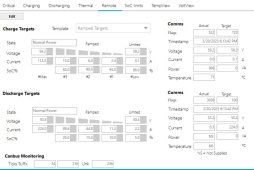
In the SMA SI CAN protocol 0x351 is required and sets battery charge voltage, dc charge current limit, dc discharge current limit, and discharge voltage ... if you don't pass these it wont work with LFP

There are a couple other fields but they don't relate around charging / discharging.
 
3.45V/cell and 0.01A @ 98%
I changed to 3.48 (since mine is offset) and 0.1 (since you can't do 0.01) and 98% ... left it alone for an hour then checked in. Voltage of the cells read 3.34-3.37 ... before this change I had 97% 56.8 0.6 and the voltage read 3.43-3.45 ... interesting. SOC still indicates it is full
 
I changed to 3.48 (since mine is offset) and 0.1 (since you can't do 0.01) and 98% ... left it alone for an hour then checked in. Voltage of the cells read 3.34-3.37 ... before this change I had 97% 56.8 0.6 and the voltage read 3.43-3.45 ... interesting. SOC still indicates it is full

That's eliminated any low-current overcharging. I'll be curious to see how it performs after an overnight cycle and full day at the new settings.
 
Last edited:
Over night morning stats, will let it run a full day and post the daily session stats tomorrow along with an update on the chart. Right now it looks like the bat will drop below 98% then the ramp kicks in and requests 2.4A and it gets right back up to 98% where it drops to 0.1A.
 

Attachments

  • photo_2023-03-18_09-13-25.jpg
    photo_2023-03-18_09-13-25.jpg
    93.3 KB · Views: 12
24hour period updates. Can't say I am surprised having previously had a similar setup where the pack never jumped above the 3.33 range ... Attached some other settings which might relate to why this is here as well as the daily session and general chart status. I did notice more discharging than charging yesterday but today's session shows it relatively even.
 

Attachments

  • photo_2023-03-19_08-10-10.jpg
    photo_2023-03-19_08-10-10.jpg
    53.5 KB · Views: 27
  • photo_2023-03-19_08-10-17.jpg
    photo_2023-03-19_08-10-17.jpg
    91.9 KB · Views: 20
  • photo_2023-03-19_08-15-37.jpg
    photo_2023-03-19_08-15-37.jpg
    56.1 KB · Views: 23
  • photo_2023-03-19_08-15-40.jpg
    photo_2023-03-19_08-15-40.jpg
    80.2 KB · Views: 23
  • photo_2023-03-19_08-15-43.jpg
    photo_2023-03-19_08-15-43.jpg
    18.8 KB · Views: 22
You have both your voltage and cut-off at 3.55V/cell. Is that your intent?

I'm not entirely sure how the taper to the limited voltage below the absorption voltage will behave.

Are you getting 1-2 hours of time at or above the bypass voltage OR above 3.40V?
 
You have both your voltage and cut-off at 3.55V/cell. Is that your intent?
https://diysolarforum.com/threads/recommended-charge-profile-for-diy-lifepo4-batteries-sticky-post.5101/ Wills post here, down at the 5000+ cycles, if you do the math you get around 3.53 v per cell. @sunshine_eggo EDIT: Default setting for bypass voltage is 3.5 when you select "Li-FePO4 Longlife" setting in the batrium CellMon Settings for Batt Type
photo_2023-03-19_16-07-13.jpg


Are you getting 1-2 hours of time at or above the bypass voltage OR above 3.40V?
The default "ramp down" voltage is the same as the bulk voltage. With that setup my pack stays pegged at 3.43-3.45 all day if the grid is connected. Then at some time during the day after the bypass limit is reset for the daily session it will very slowly ramp up over time till all cells reach their bypass again and reset the SOC. This brings the cells up to 3.5 for a lengthy period of time.

As an experiment I just reset the SoC to 85% (where my ramp down starts) to see what it does after it settles back down.

After 24 hours I can change the bypass back to the default 'long life' setting of 3.65, and the ramp down voltage to the bulk phase voltage to see what it does then as well.
 
Last edited:
Definitely not good autolevel settings. There is zero value in any balancing below 3.40V. It may actually be counter-productive.

View attachment 139701


Cell banding should be at or less than the Different Gap value. This is used to restrict the balancing to a smaller value than the gap, e.g., let's say you only wanted a 0.05V gap, and when that happened, you only wanted the worst 0.02V cells balanced to keep the balancers from hover-heating.
I changed to Auto Level and set Gap at 0.02 and Banding at 0.10V and it only bypasses single cells now and actually works quite well compared to just Bypass function. What does Bypass Banding mean?
 
https://diysolarforum.com/threads/recommended-charge-profile-for-diy-lifepo4-batteries-sticky-post.5101/ Wills post here, down at the 5000+ cycles, if you do the math you get around 3.53 v per cell. @sunshine_eggo EDIT: Default setting for bypass voltage is 3.5 when you select "Li-FePO4 Longlife" setting in the batrium CellMon Settings for Batt Type
View attachment 140345
Yes, it can't be changed, 3.5V is default. You can change low cell v cutout under Auto Level "More" button. I'm assuming this is when the bypass will stop.
 
I changed to Auto Level and set Gap at 0.02 and Banding at 0.10V and it only bypasses single cells now and actually works quite well compared to just Bypass function. What does Bypass Banding mean?

Banding is the "width" of voltages the balancers will work on simultaneously.

In my case, when I deployed my NMC bank, the total deviation was about 0.25V. 12 were pretty close, one was way low and one was way high.

Set gap to 0.02V. If I set banding to 0.01V, it would have only worked on the cells with the highest voltage within 0.01V, i.e., the single high cell.

If I set banding to 0.25V, it would have done all cells 0.02V or higher from the lowest cell. In my case, I needed 13 of 14 cells burned off. This could have over-worked the heat sink on the WM5 if I didn't have active cooling. In this case limiting the banding would have reduced the strain on the balancers.
Thanks, makes it much easier to understand. With the Core and K9's, there is a heat sink on each battery. When I was just using Bypass without the Auto Level and the current settings, the balancing would be on multiple cells, usually 8 cells, even then odds, and the K9 temp would rise quite fast. It would bypass cells that had lower voltage and it seemed a waste to me, plus it would heat up the K9 rapidly. The result was it took extended time to get balance.
 
As an experiment I just reset the SoC to 85% (where my ramp down starts) to see what it does after it settles back down.
Same old 3.3 settled voltage state, not being able to climb past with the .1A at 98% SoC.

Will now set to the non-longlife setting, ramp start / end voltages match, set SoC manually to 88 to trigger a charging cycle given the battery is at 3.3 right now, and selected default settings for charging (as I had them modified slightly for cell hi cutout. Will report in another 24 hours with new settings to see where the battery ends up and what it does. Final ramp is set to 98% and .1A still.
 
Beginning to think something is "wrong" if you will ... pack went through a charge cycle and settled down, only 2.5Ah went in during that time based off the telemetry I am seeing. It is still at 3.3-3.32 :/

I set the SoC manually to 88% so I wouldn't get a huge cutoff behavior from the start from having it below 85% which would request 112A ... looking at the reason the charging stopped it seems the bypass session mAh amount was exceeded for each cell. The SoC never got beyond 90/91 so the request was 6A when it "finished" and reset the SoC to 100% for the pack.
 
basic defaults at this point. I went through most screens and defaulted them after selecting typical LFP BUT the ramped I kept my personal settings and only updated the voltage to match the default voltage.

EDIT: Looks like my settings screeshots are compressed ... sec will fix this ... mental note, the form doesn't like wide images. @sunshine_eggo
 

Attachments

  • photo_2023-03-20_19-17-55.jpg
    photo_2023-03-20_19-17-55.jpg
    85.2 KB · Views: 31
  • photo_2023-03-20_19-25-35.jpg
    photo_2023-03-20_19-25-35.jpg
    55.6 KB · Views: 28
  • photo_2023-03-20_19-25-39.jpg
    photo_2023-03-20_19-25-39.jpg
    83.4 KB · Views: 33
  • photo_2023-03-20_19-25-42.jpg
    photo_2023-03-20_19-25-42.jpg
    71.9 KB · Views: 31
Last edited:
basic defaults at this point. I went through most screens and defaulted them after selecting typical LFP BUT the ramped I kept my personal settings and only updated the voltage to match the default voltage.

EDIT: Looks like my settings screeshots are compressed ... sec will fix this ... mental note, the form doesn't like wide images. @sunshine_eggo
A few things I see with your setting I don't like, the high voltage cutoffs are too high. This is what have set.

Batrium charging.jpg

As for your ramped charging (which I don't use), the limits are set too high.
 
As for your ramped charging (which I don't use), the limits are set too high.
Thanks for the thoughts, which limits?
I think my settings are default "long life LFP" right now ... in your settings it looks like the only active options which are different is the high shunt voltage cutout, and the cell hi cutout
 
Back
Top