BrianS
New Member
- Joined
- Mar 15, 2020
- Messages
- 44
First, thanks a ton for the quick reply. I've typed my question's in red under each of your responses below. You'll have to click on the expand button to read them and I think nomenclature is the sticky point here. I say that because in your first paragraph you allude to the fact that float and absorption voltage are settings in the charger but the following sentence it seems say that the BMS controls the charger, I'm confused...
One more item, most say you should not charge a LiFePo4 battery below freezing. In the "Protection" parameters section of the settings Overkill BMS has a field called "Charge under temp" and it is set at -1C. Is this a correct value as that figure is below freezing?
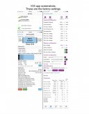
Perhaps if you could please take a look at the pic below and edit it to reflect best value for a LiFePo4 battery?

OK, so float and absorbtion voltage are settings on your charger. The BMS will disconnect the charger when the voltage rises to the Trigger value, either on one cell or the whole pack. The release value is when charging will be re-enabled.
example: using an unregulated charger, cell 1 rises to 3.650v (the high voltage cutoff, at this point the cell is over 100% charged) the BMS will disconnect/ block any more charging current. It will stay like this until the cell drops down to 3.500v, (from discharging)
You should be using a regulated charger that has a voltage limit (absorption voltage limit) set at like 14.2 to 14.4
I'm using the Renology DCC50S to charge my cells. I was unaware that there is a way to set absorption voltage in the DCC50S.
With the lithium pack that I've been experimenting with, it tends to cut off for a single cell high voltage before the whole pack gets to 14.4v, but I am using the cheapest cells I could find. (possibly mismatched capacities)I have some good cells on the way.
Inverter cutoff is a setting on your inverter which is probably not adjustable, none of my inverters have that adjustment. The low voltage cutoff (pack or single cell) will cutoff the discharge current at whatever value you set it. Recommend 2.5v per cell / 10v pack.
This terms mentioned above are terms Will uses in his "Recommended Charge Profile for DIY Batteries" I assumed these were for a BMS not the charger. My bad...
Below 3.000v per cell there is like 1% of the capacity left so if you want to preserve cell life set the low voltage at 2.9v per cell / 11.6v pack
The Overkill BMS has settings called "Cell under volt" and "Batt under volt" in which should I enter the above value? I have a 12.8v pack does that make a difference?
likewise, they are almost fully charged at 3.4v per cell.
Again the Overkill BMS has both "Cell over voltage" and "Batt over voltage" in which should I enter the above value?
A warning tho- having the BMS cutoff current can cause voltage spikes up the line that might damage your charger or load. Thats why they should be regulated so as to not reach the BMS cutoffs if possible.
The Overkill BMS does not have a Cutoff current setting but does have both "Charge over curr." and "Charge under curr." setting. Is that the same and should I change those?
The Github and reddit pages are a work in progress, I will probably polish this post a bit and put it in both places.
If I missed part of your question please let me know.
One more item, most say you should not charge a LiFePo4 battery below freezing. In the "Protection" parameters section of the settings Overkill BMS has a field called "Charge under temp" and it is set at -1C. Is this a correct value as that figure is below freezing?
Perhaps if you could please take a look at the pic below and edit it to reflect best value for a LiFePo4 battery?
Attachments
Last edited:
")