diy solar

diy solar

Finally found a LiFePO4 BMS with Low-temp Charging Protection

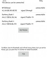
With more than 1 BMS you will want to name each BMS with its own unique name

Go to App Settings
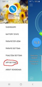
screea1a.jpg
Then Click on the Device Model and change the BMS Name
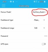
screen2a.jpg
Now when you open the app it will show each BMS with its own Unique Name.

When you open the app it will show each BMS. Just click on the one you want to open. If you don't choose which BMS you want to open in a timely fashion it will open up the first BMS it finds automatically.
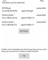
screen 1.jpg
When you want to change from one BMS to another click on the BMS you are currently connected to.
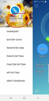
screen2.jpg
Now you will want to click on the UNLINK, which will disconnect you from this BMS and allow you to choose which BMS you want to connect to.
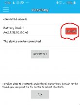
screen3.jpgscreen 1.jpg

Hope this helps.
 
I searched this thread but didn’t see this mentioned, figure this should be noted in this thread.

The Daly Smart BMS I just received - 4s 12v 200A model R05W-FL04 - does have a working low temperature cutoff. Just tested cutoff set at 15C and again at 0C, disconnects immediately when the set cutoff is exceeded.

Side-note: If the temperature sensor is disconnected entirely it interprets this as -40C. I figured it would ignore the temp sensor in this situation but it didn’t, threw me for a loop when I couldn’t get the thing to charge - it was stuck w/ an active low temp cutoff.
 
I just checking back in here - thanks for feedback. Certainly my BMS situation was only meant to be a stop-gap, however well it works (other than balancing). I cant see why having 6P would be bad for balance, other than just taking a long time to top balance given the fixed amount of bleed off but much larger than what a 100A BMS would normally run.


I was put off relay using BMS for high amps, I want a 500A capable system, max 300A realistic large long load (and yes I know it would be easier on 24v). I did look at those 250A Daly BMS - split the pack into 3 batteries - but would also need 3 monitors, will do 750A, 1C being 900A
For the usual 100A 'fet based BMS's I could use 6 to get 600A ..... and I go round in circles and don't commit to a route to sort it - especially as everything just works so well - I'm quite comfy self-monitoring my setup being its my full time house/van. It very rarely gets low SOC unless I'm specifically allowing it and monitoring it, and in summer I just charge (via BMS) to 13.6 and it mainly wanders around 80%

Awaiting the active balancer, may so a self top-balance got to strip things out and rejig them a bit when the new inverter/charger arrives
I'm not an expert but there has been discussions about how many cells in parallel. IIRC the general recommendations are 2-3 cells in parallel as a max.
 
I bought a couple of 120A JBD-BMS with uart port and the bluetooth module. (from Aliexpress, bc I'm in Europe)

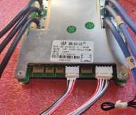
I don't like how to see the data through the APP (change between the bms...) so I'm planning to use an arduino board and connect it to a raspberry pi server (also it has my victron smartshunt and the renogy SCC wired in and getting data), the situation here is, when I order it, they gave me the option to take with UART or UART+485 and I toke the UART version (as the image below)

photo_2021-01-21_10-20-45.jpg

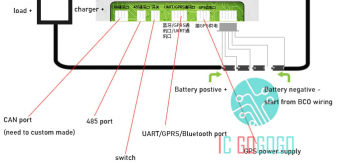
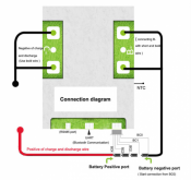
And according to the image of the diagram (below)

Sense títol.png

My CAN, 485 and switch have no connector. But I guess if I have to, as the board seems the same, I guess I could connect a connector or plug in the wires soldering directly.

My question is, It is possible to maintain the Bluetooth connected to the UART and communicate the BMS with the arduino through another port? (like CAN or 485 in case it were working, and only the connector were missing). In case it's not possible, I will not use the bluetooth and connect it to the UART (any diagrams and how to's?

Someone has some schematics?

Thanks and have a nice day!
 
This was for Android. I can't afford an iPhone! :)

Here's another question. All 4 of my BMSes came with these two wires (already plugged in). Does anyone know what they are for? Apparently this is NOT the switch, which as far as I can tell is missing on these (missing port to the right, I think)? Any ideas?

View attachment 26671

RS485 port?


Screenshot 2021-01-21 at 10.17.06 AM.png
 
Will...Or anybody else,, I was planning on building 2 separate 4s battery's using this BMS. Can I wire these battery's in series for a 24v application? I have storage restraints that prevents a 8s assembly. Specs are 2) 155ah 4s battery's. Max load will be 60 amps.
 
Can I wire these battery's in series for a 24v application? I have storage restraints that prevents a 8s assembly.
There is not much difference between 2x 4S batteries in series and a single 8S battery. The only real difference is using 2 BMSs.
What are your storage constraints (or options)? 2 separate small battery compartments? If so, how much separation?
 
the entrance of the compartment is only big enough to allow a 4s in. Both 4s battery's can sit within inches of each other once they've entered the compartment. I guess what I'm asking is will the 2 separate battery's, with their own BMS, be ok? I plan on installing a disconnect switch between the battery's for a on/ off switch for the load circuit....this will also isolate each battery from each other for charging separately with a lifepo4 12v charger.
I could use a externally mounted 8s BMS as long as it was waterproof. Otherwise I can build each 4s separately in a waterproof box.

Bottom line...while in operation will 2 separate 4s BMS's wired in series interfere with each other?
I've noticed some turnkey lifepo4's recommend no series connections. Thanks for the help....any other BMS recommendations would be helpful as well.
 
I apologize if this has been covered before, but I didn't see anything on it...

I've got two 4s 12v packs (4 3.2v 272A Lishen cells per pack, each with a 120A JBD BMS). I want to power a 3000W inverter and draw up to 200A. Would it be better to have those 200A split between both BMS, and running through both BMS (i.e. 100A per battery pack combined AFTER the BMSes and BEFORE the inverter). Or, still use two BMS for DC loads, but the max 200A going to the inverter would bypass both BMS. So the BMS still has "control" over this current, I would add a normally-open solenoid between the battery-to-inverter cable that bypasses the BMS's FETs. I assume even though current isn't going through the BMS's FETs, the sense wires would still detect an undervoltage/low SoC and thus shut off discharge. Since the voil for the normally-open colenoid is on the load side of the BMS, it would lose power, and thus, open the solenoid. Would this work?
 
Have you verified that your 200 amp load is too much for your BMS? It's within the 240 amp rating, so I would expect it to work.
Certainly no problem for the 240A rating, assuming both are discharging, but what if one battery dropped out for some reason? Would the sudden switch to 200A going through a 120A FET-based BMS be too much for it to handle? I would put a 120A fuse between the battery and BMS, per each BMS, but would that be sufficient protection? I've heard mixed things about this and that a bypass seems a better option... does seem more complicated though.
 
If a battery dropped out that would indeed be a problem. But I think it is unlikely that would happen and if it did, you would probably know it. The reason for dropping out would either be a low voltage disconnect or something so extreme that you might smell it.
 
raspberry pi server (also it has my victron smartshunt
It sounds like you might have Victron's VenusOS running on that Pi. In that case my driver should be of some help for you. Just unplug the bluetooth module and use that UART with a FTDI USB converter (a RS232 model should work) onto the Pi and install my driver.
See the link in my signature for more detail.
 
By the way, what does such a low temp charging protection do?
Just cut the available charging current, or -a bit more intelligent- derive to useless energy to heat the battery, so it could begin to charge again?
 
It sounds like you might have Victron's VenusOS running on that Pi. In that case my driver should be of some help for you. Just unplug the bluetooth module and use that UART with a FTDI USB converter (a RS232 model should work) onto the Pi and install my driver.
See the link in my signature for more detail.
Will check it in the weekend! Its not the venusOs, its a rpi with debian runing a Blynk local server. Finally I will connect the Bms to an esp32 (will need to check how, t'he esp32 don't have usb I think i will be able to connect the wires directly from uart to the pins of the board) and from the esp32 to the raspberry via WiFi (I've a 4g router on the van)


Cheers!
 
By the way, what does such a low temp charging protection do?
Just cut the available charging current, or -a bit more intelligent- derive to useless energy to heat the battery, so it could begin to charge again?
You can control the temp the BMS allows the battery to discharge and charge to protect the battery from damage. There is a temp sender that reads the battery's temp. You would need to heat the battery before the BMS cuts it off from discharging.
 
Last edited:
Back
Top