diy solar

diy solar

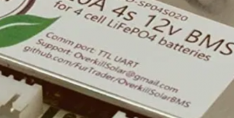
Finally found a LiFePO4 BMS with Low-temp Charging Protection

I've been messing around with an Arduinos and the UART serial from the BMS. After a lot of trial and error, I found that the BMS simply cannot be used with Arduinos which do not support hardware Serial1. Software.serial does not work. However, if you use an Arduino with an ATMega32U4 - I chose a Pro-Mini/Leonardo clone like this you will be able to connect no problem!

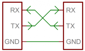
It's very simple; TX or T as marked on the BMS, connects to RX on the Arduino. RX or R on the BMS, connects to TX on the Arduino. Ground from the BMS connects to Ground on the Arduino. Supply the Arduino with 5V (note that the UART VCC from the BMS is 12V!!!) then wire up your 128x64 OLED, and you're good to go!

This is the first coding project I've ever shared with anyone; I only got into coding a few months ago and am learning... :)
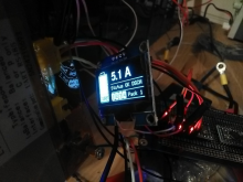
1618160422398.png

Python:
//Created by Baipin/BlPlN using Niel Jansen's Overkill Solar BMS library.
//Prints to display: SoC battery bitmap, current, error condition (error/status OK), If cells 1,2,3, or 4 are balancing.
//Must be used with a Arduino with Serial1 dedicated to UART. Will not work on any Arduino that shares UART Serial with USB.
//Arduino Pro-Mini/Leonardo with ATMega32u4 recommended.
//128x64 OLED recommended.
//Hardware: Connect TX pin from BMS to RX pin on Arduino. Connect RX pin from BMS to TX pin on Arduino. Connect BMS ground to Arduino ground. Supply with 5V. WARNING: BMS outputs 12V. Use buck or isolated PS.
//v1.0 11-04-2021

#include "bms.h"
#include "U8glib.h"
#include <Wire.h>
#include <Adafruit_SH1106.h>
#include <Fonts/FreeSansBold12pt7b.h>
//#include <Fonts/FreeSans9pt7b.h>

#define BRIGHTNESS 0x01//copy
#define BRIGHTNESSREG 0x81//copy
#define OLED_RESET 4//copy
Adafruit_SH1106 display(OLED_RESET);//copy

OverkillSolarBms bms = OverkillSolarBms();
uint32_t last_soc_check_time;

#define SOC_POLL_RATE 2000  // milliseconds

void setup() {
    pinMode(LED_BUILTIN, OUTPUT);
    Serial1.begin(9600);
    while (!Serial1) {  // Wait for the BMS serial port to initialize
    }
   
    bms.begin(&Serial1);
    bms.set_query_rate(2000);  // Set query rate to 2000 milliseconds (2 seconds)
    last_soc_check_time = 0;


    display.begin(SH1106_SWITCHCAPVCC, 0x3C);//copy
    display.display();//copy
    display.clearDisplay();//copy

}

void loop() {
    bms.main_task();
    uint8_t soc = bms.get_state_of_charge();

        digitalWrite(LED_BUILTIN, HIGH);
            display.clearDisplay();
            //display.setTextSize(3);
           
        //display.drawRoundRect(40, 5, 86, 27, 3, WHITE);
        //display.drawRect(0, 0, 70, 24, 8, WHITE);
        display.drawRoundRect(7, 0, 15, 6, 1, WHITE);
        display.drawRoundRect(0, 5, 30, 59, 3, WHITE);
        display.fillRoundRect(2, 7, 26, 55, 1, WHITE);
        display.fillRoundRect(2, 7, 26, ((100 - (soc)) / 1.8), 2, BLACK);
        //display.fillRoundRect(2, 7, 26, (50 / 1.8), 2, BLACK); //TESTING (uncomment for 80%SoC test image)
        display.setTextColor(BLACK);
        //display.setTextSize(1);
        display.setFont();
        display.setCursor(6,52);
        //display.print("1");//TESTING DIGITS
        display.print(soc, DEC);
        display.print("%");

           
     bool has_something_gone_wrong = bms.get_protection_status_summary();
    // Returns True if any protection status bits are currently active

        if (has_something_gone_wrong) {
        display.setTextColor(WHITE);
        display.setCursor(40,34);
        display.print ("ERROR! ");
        }
        else {
        display.setTextColor(WHITE);
        display.setCursor(40,34);
        display.print ("Status OK ");
        display.print(bms.get_discharge_mosfet_status()? "DS" : "! ");
        display.print(bms.get_charge_mosfet_status()? "CHG": "! ");
       
        }


    bool cell_1_status = bms.get_balance_status(0);
    bool cell_2_status = bms.get_balance_status(1);
    bool cell_3_status = bms.get_balance_status(2);
    bool cell_4_status = bms.get_balance_status(3);
   
        display.fillRoundRect(39, 48, 10, 14, 1, WHITE); //Cell 1 No Balance
        display.fillRoundRect(50, 48, 10, 14, 1, WHITE); //Cell 2 No Balance
        display.fillRoundRect(61, 48, 10, 14, 1, WHITE); //Cell 3 No Balance
        display.fillRoundRect(72, 48, 10, 14, 1, WHITE); //Cell 4 No Balance
       
        display.setTextColor(BLACK);
        display.setCursor(42,52);
        display.println(cell_1_status? "B" : "1");
        display.setCursor(53,52);
        display.println(cell_2_status? "B" : "2");
        display.setCursor(64,52);
        display.println(cell_3_status? "B" : "3");
        display.setCursor(75,52);
        display.println(cell_4_status? "B" : "4");
   
        display.setTextColor(WHITE);
        display.setCursor(85,52);
        display.print ("Balance");                  


    float current = bms.get_current();
            display.setFont(&FreeSansBold12pt7b);
            display.setTextColor(WHITE);
            display.setTextSize(1);
            display.setCursor(43,22);
            //display.print("2"); //TESTING
            display.print(current, 1);
            display.println(" A");

            display.drawFastHLine(40, 29, 87, WHITE);
            display.drawFastHLine(40, 46, 87, WHITE);
            display.drawFastHLine(40, 63, 87, WHITE);            
            //display.drawFastVLine(60, 22, 32, WHITE);
            ///display.drawFastVLine(90, 32, 32, WHITE);
            //display.drawRoundRect(40, 48, 80, 16, 3, WHITE);  
           
            display.display();
         
         
            Wire.beginTransmission(0x3c);
            Wire.write(0x00);
            Wire.write(BRIGHTNESSREG);
            Wire.endTransmission();
            Wire.beginTransmission(0x3c);
            Wire.write(0x00);
            Wire.write(BRIGHTNESS);
            Wire.endTransmission();

    if (millis() - last_soc_check_time > SOC_POLL_RATE) {
        if (soc < 30) {
            digitalWrite(LED_BUILTIN, HIGH);
        }
        else {
            digitalWrite(LED_BUILTIN, LOW);
        }

        last_soc_check_time = millis();
    }

}
 
I've been messing around with an Arduinos and the UART serial from the BMS. After a lot of trial and error, I found that the BMS simply cannot be used with Arduinos which do not support hardware Serial1. Software.serial does not work. However, if you use an Arduino with an ATMega32U4 - I chose a Pro-Mini/Leonardo clone like this you will be able to connect no problem!

It's very simple;
TX or T as marked on the BMS, connects to RX on the Arduino. RX or R on the BMS, connects to TX on the Arduino. Ground from the BMS connects to Ground on the Arduino. Supply the Arduino with 5V (note that the UART VCC from the BMS is 12V!!!) then wire up your 128x64 OLED, and you're good to go!

This is the first coding project I've ever shared with anyone; I only got into coding a few months ago and am learning... :)
This is what makes these forums so good. Don't understand it but others will...... :unsure:
 
This is what makes these forums so good. Don't understand it but others will...... :unsure:

Haha, I was in the same spot as you not long ago, trying to figure out wqhat the hell all those words meant. :p To put it simply; this is all your need for wiring the communication between the BMS and your Arduino:

1618268419992.png

Then, buy a "128x64 OLED i2c" from eBay or whatever, Google and follow the wiring diagram for that (e.g. OLED to [style of Arduino you bought]), copy my code, paste it into the Arduino coding environment (the IDE as they call it), choose the USB port that your Arduino is connected to, upload the code to the Arduino, and voila, it works!

Also... happy to report that my attempts to make the Arduino pro-micro even more power-efficient, have paid off:

By reducing OLED brightness in the registry by a bit, I can go from 25mA to 10mA. By desoldering the tiny power LED on the Arduino board, I reduced power consumption by about 5mA, by removing a redundant linear voltage regulator, and replacing with a paralleled buck DC-DC regulator for all boards, I could further reduce it by 5mA. Finally, by using the LowPower.h library and setting UART requests to every 500mS and idle-mode to 500mS which appears to occur at the bottom of the UART TX/RX waveform (or whatever you call it; the repeating pattern of communication events), then the boards consumes a mere 45mA from 100mA previously that's 55% more efficient!! Pretty great for someone who is clueless about microelectronics and coding until a couple months ago

C++:
//put this at the top of your code:
#include "LowPower.h"
#define SOC_POLL_RATE 500  // milliseconds to be corrected to 500 if different; default is probably 2000

//put this at the beginning of your code - very important so you give 8 seconds to upload code/make changes, and don't brick your Arduino LOL!
delay(8000);

//replace the default query rate with this in setup()
bms.set_query_rate(500);  // Set query rate to 500 milliseconds (0.5 seconds)

//put the following code inside the loop()
LowPower.idle(SLEEP_500MS, ADC_OFF, TIMER4_OFF, TIMER3_OFF, TIMER1_OFF,
            TIMER0_OFF, SPI_OFF, USART1_OFF, TWI_OFF, USB_OFF);
 
I've been messing around with an Arduinos and the UART serial from the BMS. After a lot of trial and error, I found that the BMS simply cannot be used with Arduinos which do not support hardware Serial1. Software.serial does not work. However, if you use an Arduino with an ATMega32U4 - I chose a Pro-Mini/Leonardo clone like this you will be able to connect no problem!

It's very simple; TX or T as marked on the BMS, connects to RX on the Arduino. RX or R on the BMS, connects to TX on the Arduino. Ground from the BMS connects to Ground on the Arduino. Supply the Arduino with 5V (note that the UART VCC from the BMS is 12V!!!) then wire up your 128x64 OLED, and you're good to go!

This is the first coding project I've ever shared with anyone; I only got into coding a few months ago and am learning... :)

View attachment 44643

Python:
//Created by Baipin/BlPlN using Niel Jansen's Overkill Solar BMS library.
//Prints to display: SoC battery bitmap, current, error condition (error/status OK), If cells 1,2,3, or 4 are balancing.
//Must be used with a Arduino with Serial1 dedicated to UART. Will not work on any Arduino that shares UART Serial with USB.
//Arduino Pro-Mini/Leonardo with ATMega32u4 recommended.
//128x64 OLED recommended.
//Hardware: Connect TX pin from BMS to RX pin on Arduino. Connect RX pin from BMS to TX pin on Arduino. Connect BMS ground to Arduino ground. Supply with 5V. WARNING: BMS outputs 12V. Use buck or isolated PS.
//v1.0 11-04-2021

#include "bms.h"
#include "U8glib.h"
#include <Wire.h>
#include <Adafruit_SH1106.h>
#include <Fonts/FreeSansBold12pt7b.h>
//#include <Fonts/FreeSans9pt7b.h>

#define BRIGHTNESS 0x01//copy
#define BRIGHTNESSREG 0x81//copy
#define OLED_RESET 4//copy
Adafruit_SH1106 display(OLED_RESET);//copy

OverkillSolarBms bms = OverkillSolarBms();
uint32_t last_soc_check_time;

#define SOC_POLL_RATE 2000  // milliseconds

void setup() {
    pinMode(LED_BUILTIN, OUTPUT);
    Serial1.begin(9600);
    while (!Serial1) {  // Wait for the BMS serial port to initialize
    }
  
    bms.begin(&Serial1);
    bms.set_query_rate(2000);  // Set query rate to 2000 milliseconds (2 seconds)
    last_soc_check_time = 0;


    display.begin(SH1106_SWITCHCAPVCC, 0x3C);//copy
    display.display();//copy
    display.clearDisplay();//copy

}

void loop() {
    bms.main_task();
    uint8_t soc = bms.get_state_of_charge();

        digitalWrite(LED_BUILTIN, HIGH);
            display.clearDisplay();
            //display.setTextSize(3);
          
        //display.drawRoundRect(40, 5, 86, 27, 3, WHITE);
        //display.drawRect(0, 0, 70, 24, 8, WHITE);
        display.drawRoundRect(7, 0, 15, 6, 1, WHITE);
        display.drawRoundRect(0, 5, 30, 59, 3, WHITE);
        display.fillRoundRect(2, 7, 26, 55, 1, WHITE);
        display.fillRoundRect(2, 7, 26, ((100 - (soc)) / 1.8), 2, BLACK);
        //display.fillRoundRect(2, 7, 26, (50 / 1.8), 2, BLACK); //TESTING (uncomment for 80%SoC test image)
        display.setTextColor(BLACK);
        //display.setTextSize(1);
        display.setFont();
        display.setCursor(6,52);
        //display.print("1");//TESTING DIGITS
        display.print(soc, DEC);
        display.print("%");

          
     bool has_something_gone_wrong = bms.get_protection_status_summary();
    // Returns True if any protection status bits are currently active

        if (has_something_gone_wrong) {
        display.setTextColor(WHITE);
        display.setCursor(40,34);
        display.print ("ERROR! ");
        }
        else {
        display.setTextColor(WHITE);
        display.setCursor(40,34);
        display.print ("Status OK ");
        display.print(bms.get_discharge_mosfet_status()? "DS" : "! ");
        display.print(bms.get_charge_mosfet_status()? "CHG": "! ");
      
        }


    bool cell_1_status = bms.get_balance_status(0);
    bool cell_2_status = bms.get_balance_status(1);
    bool cell_3_status = bms.get_balance_status(2);
    bool cell_4_status = bms.get_balance_status(3);
  
        display.fillRoundRect(39, 48, 10, 14, 1, WHITE); //Cell 1 No Balance
        display.fillRoundRect(50, 48, 10, 14, 1, WHITE); //Cell 2 No Balance
        display.fillRoundRect(61, 48, 10, 14, 1, WHITE); //Cell 3 No Balance
        display.fillRoundRect(72, 48, 10, 14, 1, WHITE); //Cell 4 No Balance
      
        display.setTextColor(BLACK);
        display.setCursor(42,52);
        display.println(cell_1_status? "B" : "1");
        display.setCursor(53,52);
        display.println(cell_2_status? "B" : "2");
        display.setCursor(64,52);
        display.println(cell_3_status? "B" : "3");
        display.setCursor(75,52);
        display.println(cell_4_status? "B" : "4");
  
        display.setTextColor(WHITE);
        display.setCursor(85,52);
        display.print ("Balance");                 


    float current = bms.get_current();
            display.setFont(&FreeSansBold12pt7b);
            display.setTextColor(WHITE);
            display.setTextSize(1);
            display.setCursor(43,22);
            //display.print("2"); //TESTING
            display.print(current, 1);
            display.println(" A");

            display.drawFastHLine(40, 29, 87, WHITE);
            display.drawFastHLine(40, 46, 87, WHITE);
            display.drawFastHLine(40, 63, 87, WHITE);           
            //display.drawFastVLine(60, 22, 32, WHITE);
            ///display.drawFastVLine(90, 32, 32, WHITE);
            //display.drawRoundRect(40, 48, 80, 16, 3, WHITE); 
          
            display.display();
        
        
            Wire.beginTransmission(0x3c);
            Wire.write(0x00);
            Wire.write(BRIGHTNESSREG);
            Wire.endTransmission();
            Wire.beginTransmission(0x3c);
            Wire.write(0x00);
            Wire.write(BRIGHTNESS);
            Wire.endTransmission();

    if (millis() - last_soc_check_time > SOC_POLL_RATE) {
        if (soc < 30) {
            digitalWrite(LED_BUILTIN, HIGH);
        }
        else {
            digitalWrite(LED_BUILTIN, LOW);
        }

        last_soc_check_time = millis();
    }

}
thanks - I'm looking to do this as well
how do you connect the rx, tx and gnd wires to the BMS?
 
thanks - I'm looking to do this as well
how do you connect the rx, tx and gnd wires to the BMS?
There should be a JST 4-pin connector soldered onto the BMS, with TX, RX, and GND clearly indicated (and an unpopulated 4th pin). Make a cable terminating in JST XH-series and attach the other end to your arduino however you wish, and you're good to go!
 
There should be a JST 4-pin connector soldered onto the BMS, with TX, RX, and GND clearly indicated (and an unpopulated 4th pin). Make a cable terminating in JST XH-series and attach the other end to your arduino however you wish, and you're good to go!
is the serial 5V or 3.3V? I was planning on using nodeMCU so may need to use line level converter?
Thanks for your help, I see info on the software but not much on the hardware interface
 
is the serial 5V or 3.3V? I was planning on using nodeMCU so may need to use line level converter?
Thanks for your help, I see info on the software but not much on the hardware interface
I forget what the serial voltage is (i.e. on TX and RX) but suffice it to say, you're connecting to the RX and TX pins on your Arduino, and it'll handle it fine. The hot/Vin/+ coming off of the BMS (that 4th and sometimes unpopulated pin) is 12 volts!!! Don't connect it directly to the Arduino; put a switching regulator inline to drop the voltage. A LM2596 or better yet, a RECOM R-28E5.0-0.5 is a good option (for the latter, I recommend adding a TVS and a polyfuse as per the datasheet's recommendations - I've never found a need for a capacitor though, if you're just powering a little Arduino).
 
yes, but I want to know if somebody has done something with the UART or RS485 port to get data to an arduino/raspberry board! :)
Did you ever get an answer? Mine have the UART and RS485 plugs. I was hoping to monitor all 4 BMS's remotely via internet. Using a raspberry
 
i’m planning on using arduino to read the BMS info

from the JBD BMS UART data port

will be using teensy 3.5 microcontroller

have read data from victron MPPT over UART with arduino before. important to verify logic level voltages ahead of time. 3.3V or 5.0V
 
i’m planning on using arduino to read the BMS info

from the JBD BMS UART data port

will be using teensy 3.5 microcontroller

have read data from victron MPPT over UART with arduino before. important to verify logic level voltages ahead of time. 3.3V or 5.0V
yes - how would this be achieved? I've been lead to believe that it can damage the 3.3V equipment
 
Device says TTL on the UART which I believe is 5V. So I need to use a line level converter to take it down to the nodeMCU 3.3V I think
1622232875482.png
 
The Arduino library doesn't seem to like NodeMCU ESP8266 architecture. I'm going to try again with a Pro Micro clone as recommended. Got one on order, with an ATmega32U4 processor.
 
The Arduino library doesn't seem to like NodeMCU ESP8266 architecture. I'm going to try again with a Pro Micro clone as recommended. Got one on order, with an ATmega32U4 processor.
Yup, I found you basically have to use a 32U4/Pro Micro. I could not and still cannot get any other microprocessor to work with it. I have never come across anyone else who was able to, even though it should work by the looks of things. But, looks can be deceiving... :p

Once I get my 2x 150A BMS I'll check the UART voltages again and confirm if they're 3.3V or 5V.

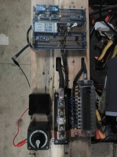
Anyways, the Arduino-powered control panel is coming along nicely!

1622396320074.png
 
yes - how would this be achieved? I've been lead to believe that it can damage the 3.3V equipment
If you want to check, and you’re using a 3.3V you can assume it’s 5V and set up a simple voltage divider and then read the ADC. The ADC will be N bits so (2^N)-1 will be the biggest value possible. 8 bit ADC means 2^8 or 2*2*2*2*2*2*2*2-1 = 256-1 = 255. Ok so you set up a voltage divider to halve the voltage on the mystery pin and then connect to the arduino ADC and read it in a loop and print it over Serial to see what it is. To calculate mystery pin voltage it’s (value from ADC) / ((2^bits in ADC)-1). But wait, that’s just the voltage at the arduino input pin. Divide that by the voltage divider reduction (if divider halves voltage need to double).

If that number comes out to be 4.9-5.1 then it’s 5V
If that number comes out to be 3.2-3.4 then it’s 3.3V


This page helped me a lot with this topic of figuring out how to identify and design properly around logic voltage levels. https://learn.sparkfun.com/tutorials/logic-levels/all

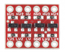
This specific device is 3usd and will shift 5v logic to 3.3v logic with TX and RX. https://www.sparkfun.com/products/12009

1622414607418.png
HV and GND go to the 5v device
LV and GND go to the 3.3v device
HV1 gets translated to LV1 and vice versa. Same for HV# to LV#

hope this helps!
 
If you want to check, and you’re using a 3.3V you can assume it’s 5V and set up a simple voltage divider and then read the ADC. The ADC will be N bits so (2^N)-1 will be the biggest value possible. 8 bit ADC means 2^8 or 2*2*2*2*2*2*2*2-1 = 256-1 = 255. Ok so you set up a voltage divider to halve the voltage on the mystery pin and then connect to the arduino ADC and read it in a loop and print it over Serial to see what it is. To calculate mystery pin voltage it’s (value from ADC) / ((2^bits in ADC)-1). But wait, that’s just the voltage at the arduino input pin. Divide that by the voltage divider reduction (if divider halves voltage need to double).

If that number comes out to be 4.9-5.1 then it’s 5V
If that number comes out to be 3.2-3.4 then it’s 3.3V


This page helped me a lot with this topic of figuring out how to identify and design properly around logic voltage levels. https://learn.sparkfun.com/tutorials/logic-levels/all

This specific device is 3usd and will shift 5v logic to 3.3v logic with TX and RX. https://www.sparkfun.com/products/12009

View attachment 51032
HV and GND go to the 5v device
LV and GND go to the 3.3v device
HV1 gets translated to LV1 and vice versa. Same for HV# to LV#

hope this helps!
Thanks I've got one of those but found out the BMS serial interface is 5V. With the Arduino there's no need for conversion. The Nodemcu would have needed it.
 
Back
Top