diy solar

diy solar

Finally, the start of my 25kw Ground Mount grid-tie system

There are a total of 96 panels. They are split into 6 series (why do people call them strings?). None of them will be combined. The fronius has a max voltage of 800v, so this is the number that I've worked around and also confirmed my manual calculations on from the fronius calculator. There will be 3 x fronius 15kw units with two inputs on each. Each fronius will receive two strings on their own MPPT.

This puts 6 series of 16 panels each. A DC+ and DC- for each series makes up 12 x 10gauge 2kv wire. I could get away with a little smaller wire, but I figured for the small cost difference that I would go a little larger due to the lower voltage drop and more flexibility down the road if I ever change anything.

Voc is 49.8v
I think they're called "strings" because they are wired in series like a string of Christmas lights.
 
OK that diagram helps. I take back everything I said about using fuses, you're running separate strings right to the inverter. Fuses would still be nice but not necessary. One thing I'd add is a DC disconnect out by the junction boxes at the array. If you ever have a fire or emergency in the building where those inverters are located, there's no way to shut down the DC current. It's also useful if you ever have to work on the DC wiring coming into the inverter, otherwise you'll have to work at night or cover the panels.

I assume you've noticed the Fronius have asymmetric MPPT input ratings. MPPT1 is about twice what MPPT2 is, so make sure the strings are low enough power to work on MPPT2.

It also looks like you're backfeeding breakers in the breaker panel. Assuming that is your main service panel I'm not sure how there can be enough capacity on the bus to allow that.
 
Thank you. I just put it in the diagram how the utility company showed on their diagrams. I'm pretty certain I double checked the MPPT ratings for both inputs, but I'll check again in a moment. I'd need a DC disconnect for each string. Any recommendations as I'll need some sort of junction box anyways.
 
@MarkSolar Fronius is showing MPPT1/MPPT2 33A/18A. I'm reading that as 33A on MPPT1 and a max of 18A on MPPT2. Plenty of room to breath since the short circuit current is 11.5A (roughly).
 
It also looks like you're backfeeding breakers in the breaker panel. Assuming that is your main service panel I'm not sure how there can be enough capacity on the bus to allow that.

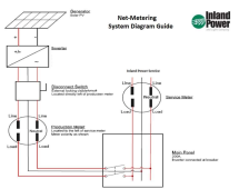
Take a look at how they have it setup in their diagram. They come out and install the production meter. I would assume they also make that connection to the main breaker panel as well otherwise the production meter install would literally be them fastening it to the building and leaving.

I took a screenshot of it so it is more easily seen.

1635963538629.png
 

Attachments

  • Inland_Net_Meter_Example_Diagram.pdf
    48.8 KB · Views: 1
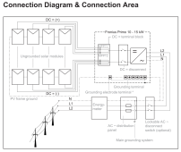
Here is a grounding diagram from Fronius. Basically showing the frame ground going back to the inverter and ultimately to the building electrode.

1635966259157.png
 
I assume you've noticed the Fronius have asymmetric MPPT input ratings. MPPT1 is about twice what MPPT2 is, so make sure the strings are low enough power to work on MPPT2.
Both MPPTs have a 1000V Voc limit.

33A and 18A current ratings per MPPT are not going to be an issue with no parallel arrays. Even if there were parallel arrays into MPPT2, the inverter will just clip the current if it gets high enough. Mine does it all the time in Spring/Summer/Autumn.

Extra string fusing is not required for these kinds of set ups.

A separate DC isolator may or may not be necessary. The Fronius has one built in (it's on the bottom of the inverter). So then it's a matter of whether you wish to be able to isolate individual strings, or need a more convenient location for emergency DC isolation. Or if it's required by code, e.g. where I am there is a (dumb) requirement for separate DC isolators at the arrays. I say dumb because they are a requirement for rooftop arrays, and guess which component fails the most in solar PV systems when exposed to the elements?
 
Yes, that is right. 1000. I'm not sure where I was coming up with the 800v. The array is built off the 1000v. Maybe the 800v was the max optimal production voltage.
 
Take a look at how they have it setup in their diagram. They come out and install the production meter. I would assume they also make that connection to the main breaker panel as well otherwise the production meter install would literally be them fastening it to the building and leaving.

I took a screenshot of it so it is more easily seen.

View attachment 71207
The diagram they provided says "Inverter connected at a breaker". The problem is that configuration would only allow for a maximum of 120% x 200A = 40A additional on the panel bus, but that has to be derated for continuous duty for PV, so that's a max of 32A @ 240V backfed through a 40A breaker. That's 7.7kW and you're wanting to backfeed somthing like 25kW as I recall. So you need to do something different. Given the work that's being done I would think putting in a line tap would would be the easiest way to provide the capacity you need. Some utilities have meter heads with a line tap built in, you could see if yours has that available. If not you'll need to add a line tap, or some way of backfeeding 25kW.

You should also ask them about the service lines coming into your meter. As I recall your house had 100A service and they are upgrading your transformer to provide 200A service. It's likely they will need to pull new service lines to support that increase. If so, that might be an ideal time to add a line tap. You can buy meter enclosures that have the line tap built in, if you did that they would hook up the new service lines to the enclosure and it would be easy to connect your PV to the line tap provided.
 
@MarkSolar

I have a 200A main breaker at that panel, which is the main panel. They are upgrading the transformer from 25kVA to 50kVA. I've gotta run out real quick, so I'll need to read through the first paragraph more closely when I get back to fully digest it.
 
@MarkSolar

I have a 200A main breaker at that panel, which is the main panel. They are upgrading the transformer from 25kVA to 50kVA. I've gotta run out real quick, so I'll need to read through the first paragraph more closely when I get back to fully digest it.
Well that's confusing. If the current transformer is only providing 100A service, it's not clear how you could end up with a 200A panel. Is it possible they don't know the size of your current transformer? That might sound crazy but when we had a problem with our service the guys who came out didn't know which transformer was feeding our house. We had done a remodel 7 years earlier and the electric company moved us to a different transformer that was more convenient for them. Their drawings still hadn't been updated after 7 years. So you might see if you can read the writing on the transformer and verify the size. Also, depending on what kind of meter enclosure you have, it would be interesting to look inside and see what size service entrance cables they are using.
 
If you say 25kVA = about 25,000 watt

P=IV
25,000 / 120V = 208A

From my understanding kVA is basically the "theoretic value" of 1A at 25KV. This would then need to be stepped down in the transformer where you would lose some efficiency, but I think the idea is there.

Let's then say that each inverting is MAXING out at 240v with 15kw each.

P=IV
45,000 Watts / 240v = 187.5A

Just writing those numbers make me excited to get this going! haha.

They've checked the existing wiring size from the transformer to the house and deemed it of appropriate size for the system. I would think that if the main breaker had to be changed then it could be once the transformer is upgraded to 50kVA.

With the bifacial aspect, it is possible I could be hitting 100% capacity for several hours a day in the summer months.
 
Last edited:
I agree with that completely. That's an error on my calculation for sure. Then I have no idea why there would be a 200A breaker in the box then.

Upgrading to a 50kVA would do the trick though.

Theoretical values Transformer:
50,000W / 240V = 208.3A

Max PV output, theoretical
15kw x 3 = 45 @ 240v
45,000W / 240V = 187.5A

This is not taking into account any losses in conversions. I think this should be correct and not what I listed above.

Looks like I have room to add a few more panels :eek: JK
 
The issue is that you can only backfeed 32A @ 240V into a 200A breaker panel. That comes from the NEC restrictions on multiple power inputs to the panel. You're correct, you will be supplying almost 200A from your PV system, which is why you need to avoid backfeeding your panel and will need to use a line tap. The line tap sits between the electric meter and your service panel, so it does not backfeed through the panel. I don't understand how large a line tap can be as a function of the size of the service entrance cables that the power company runs to your house. Hopefully someone on the forum knows that, or you could ask the utility company. Have they assigned an engineer to your project? When we moved our electric service the utility company assigned an engineer that really did a nice job finding the easiest way to do things and clearly explained what they were going to do.
 
The issue is that you can only backfeed 32A @ 240V into a 200A breaker panel. That comes from the NEC restrictions on multiple power inputs to the panel. You're correct, you will be supplying almost 200A from your PV system, which is why you need to avoid backfeeding your panel and will need to use a line tap. The line tap sits between the electric meter and your service panel, so it does not backfeed through the panel. I don't understand how large a line tap can be as a function of the size of the service entrance cables that the power company runs to your house. Hopefully someone on the forum knows that, or you could ask the utility company. Have they assigned an engineer to your project? When we moved our electric service the utility company assigned an engineer that really did a nice job finding the easiest way to do things and clearly explained what they were going to do.

I am going to contact the guy I've been working with at the utility company. He had my one-line sent over to their engineering department. He stated everything was "a go" except the inverter. I'm not sure if they were accepting the system as is or if they would make a few minor changes. Hopefully I can get some answers tomorrow regarding this. These are all the "medium" sized details that I hadn't looked at yet because I had no idea if this would go through or not. It very much so looks like it is going to go through.

What would a "wire tap" on the meter look like? I'm going to head out and take a look and also make sure I'm remember the breaker size correctly as well.

The breaker definitely says 200 right on it. I even had it inspected after putting in a minisplit in the garage there where all of this will be taking place.

They must be doing a tap, based on what you said.

Edit, again: I think the grounding issue can mostly be said to be solved for now. I need a large ground wire to run through my conduit. period. I've prepared for those costs, but I did save about $1200 on the inverters today from a new quote, so I'm ahead of the game.
 
Last edited:
The drawings I see here don't clearly indicate total inverter wattage, circuit breaker rating, breaker panel rating.
So hard for a reviewer to have noticed if anything exceeded spec.

"Line side tap" is a Y connection between meter and main breaker.

Normally, a breaker panel can be backfed with PV breakers located at the far end, PV breakers plus main breaker not exceeding 120% of busbar rating.
I think I've heard of a "PV combiner" usage of a panel with no loads, just main breaker and PV breaker, not subject to that rule.

If you had a 200A panel with 100A main breaker, you could have 100A PV breaker. Of course, should run 80A max continuous.
Don't know you can find a 100A main breaker for a 200A panel. But you could use a 100A fused disconnect and a main-lug panel.
Maybe as a PV combiner panel connected by line side tap, it would be allowed with 200A main breaker and 3 breakers for your three inverters.

If you used a Square-D QO panel as your main panel, it has 225A busbar. 225A x 1.2 = 270A
There is a 150A main breaker available. That leaves 120A for PV breakers, e.g. 3x 40A or 2x 60A
You could also have house loads on that panel.
 
I think the next step here is to find out how the utility company plans/wants to have this connection made. From there I can hopefully take your guys' ideas and suggestions to come up with a solution. I am quite certain I will have to have this all figured before I submit documents for the electrical permit.
 
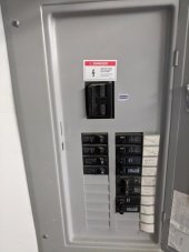
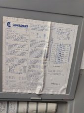
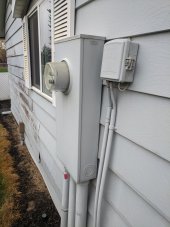
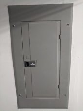
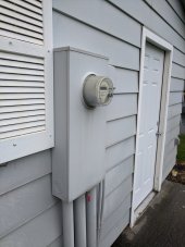
Just a few images of the breaker panel and the meter location. The panel itself is a 200A panel with a 200A breaker. I have a message out to my contact at the utility company in regards to how they want to handle the incoming power from the inverters after the production meter.

IMG_20211104_092557.jpg

IMG_20211104_092551.jpg


IMG_20211104_092525.jpg


IMG_20211104_092536.jpg
 

Attachments

  • IMG_20211104_092518.jpg
    IMG_20211104_092518.jpg
    129.9 KB · Views: 3
Back
Top