diy solar

diy solar

Finally, the start of my 25kw Ground Mount grid-tie system

@Hedges THanks again. They are the Fronius Primo 15kw inverters (3 of them in total for the install).

I'll need to do some more thinking in the morning.

@MurphyGuy Thanks! I'm over in WA or I'd take you up on that! I appreciate the assistance everyone!
 
Well, that explains your need for 200A disconnect switch and line-side tap :)

15kW split-phase / 240V = 62.5A
62.5A x 1.25 = 78A --> 80A breaker
80A x 3 = 240A protection appropriate for main.

But you only have 200A. Hope some of the panels are of different orientations, to reduce peak current.

62.5A x 3 = 187.5A
200A / 187.5 = 107%
You would only have 7% headroom over continuous current, could trip on a hot day or if wires get hot.
Oversize wire to main fuse/breaker could help. Cooling fins or forced air?
What is your main (200A) over-current protection for this circuit, anyway?

Just hope you don't get an $8/kW/month fee like California PUC plans to award PG&E from us evil greenie rooftop PV system owners.

15kW x 3 x $8/kW per month = $360/month
 
Since it will be a "meter tap" it won't run through my main breaker panels unless I were actually using all that power in the house/buildings. Even then, I have 3 separate breaker panels that feed from the meter. One that feeds the building the meter is on and two that feed the actual house. So.... From the meter tap, power has 3 ways to go in the means of me utilizing it. Of course, I won't use all that power so the rest just goes to the grid and will never see any of those panels.

They are 16 x 450W series, two per fronius inverter. That would be 14,400W PV per fronius 15k. They are bifacial, so I might get a little extra. Take into consideration losses etc... I'm sure I may be around 14kw PV on each inverter.

I won't quite be maxing everything out, but I'll be building everything out to be able to handle 200A+

For AC This means the transfer / shutoff switch, breakers, cable, junction boxes etc.... Do I need breakers, or would it be suggested, if I have a fusible switch?

The PV side actually seems to be the easy side. Hook up the panels, hook them to the inverters and pretty much done.
 
You need "service entrance equipment" connected to the meter.
That could be this 200A switch, or a 400A breaker panel with 200A main breaker.

If you used a 400A breaker panel with 200A main breaker, it would have three 80A PV breakers. Difficulty is how you would connect the required visible blade switch to disconnect all inverters.

I think a 200A switch with fuses is what you want for service entrance. The fuse protects utility line feeding it from short circuits that might occur on your side of the switch.

Each of the three 15kW inverters would need its own fuse or breaker of 80A or so. Wires would be at least 4 awg.
Even if you ran 2/0 cable to the inverters, the 200A fuses are higher than what inverter specs will allow.

450W x 16 x 2 x 3 = 43,200W
43,200W / 240V = 180A

200A equipment has only 10% headroom above 180A. Fuse/breaker should have 25% headroom to avoid nuisance trips. Hot weather, heat inside the box from the fuse or breaker's thermal element and from the wires reduce the current at which they trip. If switch and fuse were rated 225A, that would be sufficient.

If all panels have same orientation, that is where the system will be operating. If multiple angles (e.g. South East for one string on each inverter, South West for the other) then peak will be about 0.7x as high, 126A max.
 
They are all facing south (180*). I looked a little at changing the orientation, however with the way my utility company does import/export (1:1) and the space provided that I would need to eliminate shading of arrays from each other (47* lat), it just didn't seem too feasible. I have to put the arrays 42 ft. apart so they don't shade each other. Even then, it is possible I could get a little shading for a few minutes in the morning.

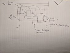
I think What I'll do is draw something up on paper to actually start getting some of this designed out and laid out on the freestanding rack.
 
A very rough sketch. I need to get the production meter base and see what I can feed it in terms of wire. I'm guessing probably just "one feed" and not all 3, which means I'll need to "combine" the lines from all fronius units prior to the production meter. If that's the case then perhaps I could add a DIN to the transfer switch and combine there on the outlet side to save on having to add another junction box.

IMG_20211216_082155.jpg

edit: the horizontal lines are mounting rails, whatever the technical term for those would be. lol
 
Disconnect, whether fusible or not, is either 2 pole or 3 pole.
You couldn't take 3 circuits from production meter then switch (both poles) of all three with one switch. Need switch before one circuit branches to three.

Take one circuit, 2/0 or larger, to fusible disconnect. After that branch to three fuses or breakers.


Maybe two holders for three fuses:


And six 80A fuses:


DIN rail fuse holder. Holder is cheaper but currently unavailable from this vendor. Fuse is more expensive.
These are rated even higher than class T.


Class T is a good fuse for service entrance. Something lesser should be sufficient for branch circuit to inverter.

Looking for other types, here are some lower priced 100A but higher priced models of 80A.


There would be more economical choices for 70A.
 
They are all facing south (180*). I looked a little at changing the orientation, however with the way my utility company does import/export (1:1) and the space provided that I would need to eliminate shading of arrays from each other (47* lat), it just didn't seem too feasible. I have to put the arrays 42 ft. apart so they don't shade each other. Even then, it is possible I could get a little shading for a few minutes in the morning.

If an array to the West faced partially West, and to the East faced partially East, they wouldn't shade each other.
Or, some could have a different tilt, although angle doesn't change as much with seasons as with time of day.

Doing something to keep main 200A fuse cool would help. Vent holes with bug screens (and covered so rain doesn't get it.) Thermostatic fan. If it still blows, program inverters to limit output.

Page 8:

"4. Cooling air correction - Kv EV fuse links may be mounted in a vented enclosure, with additional cooling provided by an electric fan to help dissipate heat. Please note that the airspeed is measured across the fuse link and not the across the fan."


Normal design practice is for thermal fuse/breaker to be sized 25% higher than max continuous current.
 
I definitely don't mind building out the new equipment to handle the +25% or even more. That's not a problem at all.

The concern on the shading was shading the southern facing array with an east / west facing ones nearby.

I'll need to comb through that information when I have more time later today and put together another "drawing" with more details.

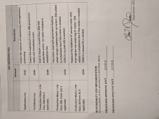
I am responsible for the production meter base. The PUC only provides the actual meter itself.

IMG_20211216_092927.jpg
 
Is the "320" rated for a 320A? If so, that may be the best option, however I am also inclined to do the production meter that would allow battery backup down the road.
 
Looking at thepowerstore as I finalize my order. I'm thinking maybe putting these at the arrays:

One on each side. There are only 3 "strings" on each array. I'm not sure what the actual rating is as it contradicts itself and says 600v, 1000v, and amperage as well.

Scratch that, those aren't rated for 1000v, look up the part number online.
 
Last edited:
Update:

Inverters, 10 gauge "dual pass" wire, crimpers, and a few other small miscellaneous things purchased from TPS (thepowerstore). The last major things to finish buying are really just the panels and some junction box type of stuff. I ended up going with 2 x 2500' spools (1 of each color). After some measuring, my runs are about 30' more than I originally anticipated. It seemed like the best route despite the higher price I ended up paying for the larger spools and dual pass.

I finished purchasing the rest of the conduit. I saw prices jumped on conduit another 30% or so and they were still the "old" price at lowes so I just said screw it and went and bought all the conduit I'll need. If I need anything it'll just be a joiner or a stick. It was about another total amount nearly 600' of conduit between the 3/4, 1.25, and 1.5".

I was supposed to get the rest of the ground screws a couple weeks ago or so, but that never happened. It has been single digits (F) during the day and below or at 0 at night. It is a little warmer now, but I think the ground may be too frozen to put down screws. Not to mention there is about 6" of snow on the ground. At least I got what I did in the ground for my own sanity and proof of concept while I sit all winter and twiddle my thumbs.

The break from the solar install will give me time to focus on other important things non-solar related.

edit: If I hadn't mentioned, the 50kVA transformer was installed as well.
 
Last edited:
TPS ended up telling me they couldn't get the red AFTER I paid for the order. That was quite disappointing.

I mostly had no choice but to go with two spools of black. NEC states that I can have same color conductors if they are properly labeled at the termination points. I have access to such labeler, so that is the route I went (reluctantly).

With the way the cost of things are going up, supply problems, and whatever else you can think of, I wanted to get the bulk of everything on order ASAP. While I'm def paying higher than a year ago by a far shot, I still feel good about where the cost of the project is landing. The numbers still work out great for me with an ROI within 10yrs after the ITC. That is with no electricity cost inflation accounted for.
 
Update: the rest of the ground screws have shown up at CED. I'm trying to find a good weekend to get the rest of them installed. I think the ground will be workable with the weather we have had here. I'd definitely like to get this aspect of the project done.
 
I have just recently found that sunmodo's configurator is not super accurate. I have to pull ground screws and rework everything. I have to order an additional 16 ground screws with the associated parts that come with them. I am also finding other discrepancies in the numbers on the configurator compared to what I actually need. I really thought it was a set it up and forget purchase until it got here. I'm extremely glad that I found all of this out now instead of after the entire frame was assembled.

I can't recall, did anyone that used the sumodo system do portrait? It also appears that the sumodo rep (not CED) took my BOM and modified it because they know the BOMs the config spits out are not entirely accurate. While doing so, he/she also botched those numbers as well.

Do I just need one "mid clamp" on each side of the panel? or would there be four mid clamp places on each panel? I am digging through documents now to try find. From what I see there is just one in the middle of each panel and then an end clamp on the end over every rail that would actually clamp down the ends of two panels since they share a rail.

I would have 25 rails per array (2portrait x 24 columns).

I am not certain why I would need the "shared rail adapter kit" K10176-001. It references being used for mounting landscape panels on EW rails. I mean, I suppose I am mount portrait on NS rails. It still doesn't look right though. I pretty much have the weekend to get this figured out.

I found this catalog to be pretty nice to see and get a little explanation as to what things are. Although, it is a bit out of date.
 
Hopefully you guys can help out on this one. I am not sure which mid clamp I would need. I am doing portrait (2p) and the rails run in the same direction as the length of the panels (hopefully that makes sense). The rails will run with the slope.

1642825631364.png

1642825656955.png

The sunmodo configurator calls for the bottom one (shared rail adapter) and the changed BOM by sunmodo calls for the top one.

To me, they both look wrong. haha. The bottom one seems as if it would add height to the rail where the top one seems to have the wrong orientation if you were to slot it into the rail.
 
This is the end clamp that would need to go on the end of each rail, I believe. It would be responsible for clamping TWO panels since the panels will share a rail. Lining this up is going to be a bi***

1642826146422.png
 
It's not too late, I could go landscape. It changes just about nothing dimensionally for me. 2 columns of two in portrait is pretty much exactly square with 4 high in landscape. I went with the portrait due to those saying snow/ice likes to get caught up on the ridges between panels. Thus, portrait reduces the horizontal lines substantially.
 
From looking and thinking on it quite a bit. I'm quite certain I have to use these, however once I use these then that "shared rail adapter" has to be used for every single clamp because it appears to add a height profile on top of the rail. The other clamps that don't use that shared rail adapter seem to NOT add any height profile.

1642905999530.png

1642906077562.png


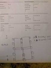
Does anyone know how many locations on each panel they have to be bonded?
 
The documentation regarding clamps is absolutely awful and pretty much NILL. This is what I've gathered should be done. To me, it seems strange not to put a clamp on the top edge and bottom edge of the panels.

IMG_20220122_190139.jpg
 
Back
Top