annafromarizona
New Member
- Joined
- Feb 9, 2022
- Messages
- 30
Hi
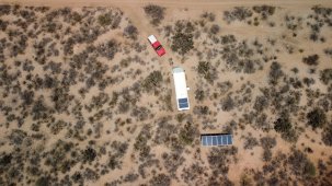
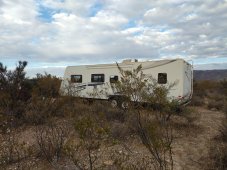
Trying to live off grid in southern Arizona.
Now, just have to put all the pieces together of my solar system. Oh, boy.
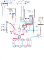
I have:
Victron multiplus 24V/3000 Watt Inverter
Victron MPPT 150/85 charge controller
6 - 305 Watt solar panels
8 - 200ah 3.2V lithium iron phosphate battery cells (w/BMS)
Battery monitor
Battery on/off switches
300a and 400a fuses
MC4 connectors/ solar panel wiring
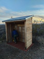
A wooden shed
Still have to source:
Whatever the heck wiring to go between the charge controller/Battery/inverter
circuit breakers (PV-charge controller)
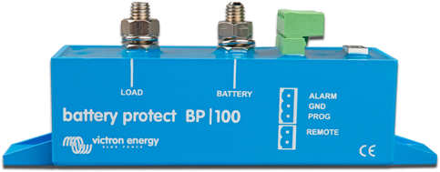
Battery protection device
grounding rod/copper wiring
Hope you all are having a nice warm winter!
Anna
Trying to live off grid in southern Arizona.
Now, just have to put all the pieces together of my solar system. Oh, boy.
I have:
Victron multiplus 24V/3000 Watt Inverter
Victron MPPT 150/85 charge controller
6 - 305 Watt solar panels
8 - 200ah 3.2V lithium iron phosphate battery cells (w/BMS)
Battery monitor
Battery on/off switches
300a and 400a fuses
MC4 connectors/ solar panel wiring
A wooden shed
Still have to source:
Whatever the heck wiring to go between the charge controller/Battery/inverter
circuit breakers (PV-charge controller)
Battery protection device
grounding rod/copper wiring
Hope you all are having a nice warm winter!
Anna