diy solar

diy solar

Forcing Sunny Island SOC

Ai4px

New Member
Joined
Feb 20, 2021
Messages
227
I'm running a home brew pair of LFP batteries with two BMSs. I've programmed the Sunny island 6048's to shut off at 42v. I'm not using the current shunt because I have two inverters, two batteries and a pair of morning star charge controllers. I would have to add another busbar into my system to get all the system current in/out thru one shunt. Despite the battery voltage being 53.3v and the morning stars keeping the battery pretty full all day, the SI shut down when it thought SoC was 15%.

So is there a way to make sunny island ignore it's own SOC estimate?

I understand there's a raspi program to communicate with the SI and you can set it up as a lithium battery. but what happens when the raspi fails? I'd like to keep this as simple as possible.
 
Sounds like your SI is interpreting battery voltage incorrectly.

How many LFP cells in series?
You are running the SI's in Lead Acid mode?
 
Yes.... my batteries don't talk to the SI.... is there a solution? Should I just switch to li-ion mode?
 
Li mode require a bms. If none , it shuts down.
What the island is seeing is .... soc goes down. You haven't told it that the batts are being recharged. So , it shuts down.

I dont have the manual handy , so I cant point you to the codes.

Bigger question.

You have 7 grand in your setup. Why wouldnt you invest another 250 bucks and have the system run like it is supposed to ?
 
If you have DC coupled PV (or other sources, or DC loads), SI is supposed to have a way to track current in and out. If SI never works as a charger (no grid or generator input, no AC coupled PV), then maybe you can get away with just voltage as an indication of SoC.

Why don't you connect a battery shunt? Then, SI can estimate SoC.
Nothing wrong with adding a busbar. Mine is a copper bar with holes through, and a bolt holds one ring terminal on top, one on bottom.
You might be able to stack five ring terminals on one long bolt and skip the busbar. I might put shunt in middle, two SI around that, two charge controllers around those. Opposite side of shunt gets two batteries.
Hardware. That's the simplest solution. Don't know for sure how SI will respond to lithium voltage profile, but at least current in/out should look OK to it.

I prefer AC coupled (Sunny Boy). But then, SI would be performing the charging, so would need settings compatible with the battery (including zero temperature coefficient if faking it as VRLA)

I don't think Li-ion mode will work unless you implement a compatible BMS with communication.
 
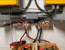
Thanks for all the input guys.... You've steered me where I was resisting going. I have ordered another busbar to attach the NEG from batteries so I can insert a shunt in between all the batt NEGs and the sunny islands. When I had lead acid, I only had ONE battery so the shunt was in there. I'll have to dust it off and install. Here's my busbars as they are today.

The smaller red/black coming in there is from the morning star... I guess you could say that's the root of the problem... actually the root is me not installing the shunt.

1626017475708.png
 
SI battery cables in plastic conduit - SMA manual recommends not to do that. Depends on gauge and temperature rise, of course.

What fuse or fuses?
I have on battery string, fan to two class T fuses, each fan to two SI

Cover over the positive busbar would be good. Piece of recycled radiator hose?
People here laughed at me for my (even closer) unfused side of + and -, I plan to mount plexiglass between them to address that.
 
You've got a negative busbar. All you need is two battery cables landing on shunt.
Maybe busbar can bolt to shunt, otherwise one ore cable.
 
You've got a negative busbar. All you need is two battery cables landing on shunt.
Maybe busbar can bolt to shunt, otherwise one ore cable.
Eventually I plan to have 6 sets of batteries... right now I have two active and one being built on the bench, so three really soon.... too many to land on a bolt into the shunt.... so I have ordered another busbar for that NEG bus.

Thanks for advice on the plastic conduit. temperature rise isn't too severe.... like non existent even at 12.5 kw. I could feel a little slight increase in temp on one of my 2/0 battery cables yesterday when pushing 130amps thru it... but it was barely detectable.
 
130 amps isn't 130 amps. Also, it takes a long time to heat up wire.
Yes, 130A (or the 12% higher I now calculate due to ripple current) should be well within 2/0 ampacity, even in bundle or conduit. Maybe SMA's advice was based on minimum cable. Mine are draped in the air the whole way, yours half way.

Have you calculated 130A based on continuous full load, minimum battery voltage, inverter efficiency at that voltage?
Multiply by 1.12 because there is a large ripple component, resulting in higher RMS current and heating of cable vs. mean current which delivers power. RMS is what matters for fuses, too.
So my two Sunny Boy inverters are outdoor. I am contemplating adding Sunny Islands, but where are you guys putting your battery cells and BMS? Is there an IP57 rated battery box you are using?
I need enclosed space for 64 280ah cells and 4 BMS's. Or are you doing long runs to your batteries?
Or should I assume those that are using DIY batteries are doing it all indoors?
 
Battery cables to inverter should be short, for minimum voltage drop at full wattage and at surge wattage. I have about 7' of 2/0 cable from busbar & fuses to each Sunny Island.
European model Sunny Island are rainproof (no toggle breaker and no SD card). Maybe those will come to the US eventually.

I noted that SI 6048US has the same OptiCool enclosure as their 3R Sunny Islands. The enclosure is also gasketed at the bezel around the controls. What I did was tape a sheet of silicone over inside of the enclosure. That makes it raintight, and I can still work the breaker (but not replace SD card.) I left a square of the stiffer plastic carrier that came with it attached to the silicone, as a tougher material to protect from sharp corners of breaker handle and SD card.
I hung my Sunny Island under a deck, but water can fall through. I also put corrugated roofing under deck, to spill water away.

DC Solar put Sunny Island in metal boxes (without following ventilation and spacing guidelines.) Other trailers have a flap attached to Sunny Island enclosure over the controls.

My AGM batteries are also under the deck, and have a corrugated sheet over them. Moderate Bay Area weather, so just shade and ambient air should be good enough for them.

I think most people are putting LiFePO4 indoors.
I think you should have them outside, far enough from house to let them burn up harmlessly. Roofing material would keep rain off. Earth sheltering could control temperature, or maybe insulate and make mostly sealed.

BMS probably should be kept in dry air, but with cooling. Possibly sealed in a box but with heatsink conducting to an aluminum enclosure (or through steel to an aluminum heatsink.)
 
Back
Top