diy solar

diy solar

Fuse/Circuit breaker Sizing and placement.

FilterGuy

Solar Engineering Consultant - EG4 and Consumers
Joined
Nov 26, 2019
Messages
7,906
Location
Los Gatos CA
I am starting this thread to discuss Fuse/Circuit Breaker Sizing and placement.

Edit: Updated the rule of thumb based on feedback in a later post from @JoeHam
My rule of thumb is the protection Device should be the lower of 1) The capacity of the power source or 2) 1.25 x the expected current on the wire.

Edit: Added info about wire sizing and Fuse Size.
All of the circuit (including the return) must use wire that is large enough (or larger) to handle all of the current the fuse will allow.

Note that adding fuses that are larger than needed means you must also use wire that is larger than needed.

This is large enough to prevent nuisance trips/blows but will still offer adequate protection.

I have noticed others use a different rule of thumb, so this might be an interesting discussion.

The following several posts are based on how I decide where protection devices need to be placed.

Edit: Added the following:
Here is a link to the slide deck in case someone wants a copy.
Edit: The deck was updated on 2/20/2020
https://docs.google.com/presentation/d/1720u-tB3Ey3bvsO4Itk3pmpdhtBdpd14ViiNGqX4U1o/edit?usp=sharing
 
Last edited:
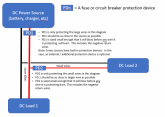
Placement of DC Fuse or Circuit Breaker protection Devices.
  1. Protection Devices should be sized small enough to prevent *any* wire it is protecting from smoking/burning
  2. Protection Devices should be placed as close to the power source as possible

1581795756000.png
 
Last edited:
Fuses on device inputs
Edited to clarify that I am talking about input fuses.
1.Device fuses/breakers on the input of a device will prevent a bad device from burning/smoking due to an internal Fault/short.
2.Device fuses/breakers on the input of a device does not prevent a device from going bad due to overload.
1581795881137.png
 
Last edited:
  • Like
Reactions: Dzl
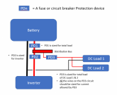
Inverter
1.Inverters are often the largest load in a solar system, and therefor have the largest wires from the battery.
2.IF the inverter is the only load, a single protection device sized for the needs of the inverter is sufficient.
3.If there are additional loads, a protection device separate than the battery protection device should be used.
1581712876036.png
 
Shared Protection Devices
EDIT: The following line was added and the diagram updated.
1. It is best for each load to have it's own protection device (Don't share protection devices)
2. If multiple loads are on one protection device, all the wires and protection device should be sized for the total load (Including the return wires)
1581718401943.png
 
Last edited:
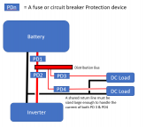
Shared Return Lines
1.Sharing return lines for multiple protection devices should be avoided.
2.If return lines are shared, they must be sized large enough to handle the combined current allowed by the multiple protection devices
1581717011162.png
 
Last edited:
Inverter/Charger
1.An inverter charger can be either a load or a source… this makes it tricky.
2.The inverter load is always larger than the charger source, so the protection device and all the wires should be sized for the inverter load.
3.The protection device should be placed as close to the battery as possible
4.The inverter/charger must have internal protection for the charge current
1581717187607.png
 
Last edited:
Here is another way to think about where to put a protection device.
Go through all the circuits and at every point imagine a short circuit between positive and ground.
  • If there is a circuit protection device between the short and ALL power sources that is small enough to protect all the wires in the path, it is probably safe.
  • If there is a path to a power source that does not have a protection device small enough to protect all of the wires in the path, it is a dangerous circuit.
 
While I completely agree that the fuse is there to protect the wiring from catastrophic failure I will note that some people do use the fuse to protect a device.

Without judging whether that is proper I will note that there has been some bleed over of the 1.25x rule of thumb. Not a good idea if trying to protect a device.
 
While I completely agree that the fuse is there to protect the wiring from catastrophic failure I will note that some people do use the fuse to protect a device.
I used to think fuses on the input could protect devices, but have changed my thinking over time. What is a scenario where the fuse would protect the device? Every scenario I can think of where the fuse would blow, requires a failure inside the device. Having said that, if a device does fail, the fuse will help prevent the failure from totally destroying the device....and therefore it might be repairable.

Fuses on the *output* of a device could definitely protect a device from harm. I will go back an udpate my post about device fuses to make it clear I am talking about fuses on the input.
 
Without judging whether that is proper I will note that there has been some bleed over of the 1.25x rule of thumb. Not a good idea if trying to protect a device.

Yes, I suppose if the device is rated at producing N amps, a 1.25*N fuse might be too high and let a short damage the device. Good point. I'll update my post with something like this: The fuse should be the smaller of 1) The capacity of the power source or 2) 1.25 x the expected current on the wire.
 
I do not have a lot of experience with large solar panel arrays but the general rules outlined above should still apply. (My experience is with smaller solar, boats and micro-hydro)
If someone with more experience could add anything specific to fusing solar arrays, I would appreciate it.
 
One thing that can make fusing on a solar array challenging is that the Imp (Max Power current) is typically pretty close to Isc (Short Circuit current) Consequently single panels or series arrays have a fairly narrow band where a fuse can make a difference. If it is below Impp it will pop too soon if it is above Isc it will never pop. If the panels are in parallel, the difference can start adding up and that gives you more room to play with.

How do people deal with this?
 
The fuses on panels arrays are mostly to avoid the other strings dumping a lot of power in a bad panel (so heat, then fire...).

It's not to protect the wires or source (panels) like we usually do as they are naturally self limiting.

If you have only one string of panels a fuse is still somewhat useful to protect against lighting. But not on its own, you need other protections too, and even that will probably not be enough in case of a direct strike...

To help make this thread complete, could you provide some guidance on this?
 
I always find that it's better to think of the fuse protecting the cable, rather than the device. For a start most devices have their own protection and thinking in this way makes you focus more on cable sizing, shorting risks etc.

@FilterGuy I like your point about considering the return cable spec potentially having to cope with all loads cumulatively. This would also be important considering P=I²R losses because current out may well be different to current back in this case.
 
Back
Top