


Hello,
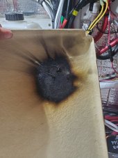
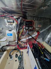
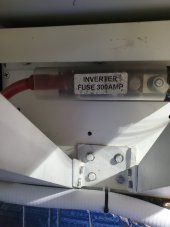
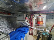
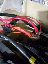
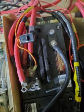
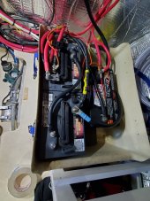
This is my first boat that has a solar charger and an Inverter setup. I started using the boat in May of this year. The Inverter is original from 2000 and the Solar Panels have probably been on the boat for 10 years or so but not 100%. Anyway this weekend when we had a heavy load on the inverter I smelled something burning. I quickly climbed into the engine room and had smoke coming from the battery box. When I opened the cover the inline fuse from the solar charger was melted and glowing red. It charred the top of the fiberglass battery box which was close to igniting. Luckily I caught it in time but now I am looking for some help on the why?
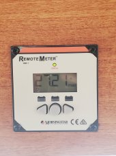
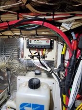
The solar charging unit is the Sun Duo SSD-25 by MorningStar. The system is connected to the house battery bank as well as the starting battery. The Inverter that runs on the house side is the Xantrex SW3000.
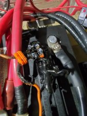
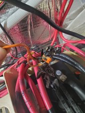
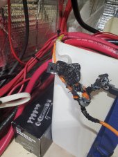
The incident happened when my wife was preparing breakfast. She used the toaster oven for a few minutes and then when that was done kicked on the microwave for a few minuts so there was a heavy load on the inverter. I am assuming the inverter load somehow was pulling amps through the solar wire and over heated it? The charging wire from the solar charger with the inline fuse is only a 12 gauge wire with a 25amp fuse. I believe there should be a 10gauge wire for a 25amp fuse so that may be part of the overheat / melting point on the fuse assembly. Not sure if putting that kind of load on this setup is not good. Looking for some help on how to determine why this turned to a near fire instead of just blowing a fuse. Any help would be appreciated.
This is my first boat that has a solar charger and an Inverter setup. I started using the boat in May of this year. The Inverter is original from 2000 and the Solar Panels have probably been on the boat for 10 years or so but not 100%. Anyway this weekend when we had a heavy load on the inverter I smelled something burning. I quickly climbed into the engine room and had smoke coming from the battery box. When I opened the cover the inline fuse from the solar charger was melted and glowing red. It charred the top of the fiberglass battery box which was close to igniting. Luckily I caught it in time but now I am looking for some help on the why?
The solar charging unit is the Sun Duo SSD-25 by MorningStar. The system is connected to the house battery bank as well as the starting battery. The Inverter that runs on the house side is the Xantrex SW3000.
The incident happened when my wife was preparing breakfast. She used the toaster oven for a few minutes and then when that was done kicked on the microwave for a few minuts so there was a heavy load on the inverter. I am assuming the inverter load somehow was pulling amps through the solar wire and over heated it? The charging wire from the solar charger with the inline fuse is only a 12 gauge wire with a 25amp fuse. I believe there should be a 10gauge wire for a 25amp fuse so that may be part of the overheat / melting point on the fuse assembly. Not sure if putting that kind of load on this setup is not good. Looking for some help on how to determine why this turned to a near fire instead of just blowing a fuse. Any help would be appreciated.
")