diy solar

diy solar

Fuse Types for LFP Pack and Inverter

carbon60

Solar Enthusiast
Joined
Jan 8, 2021
Messages
236
Location
Ottawa
So I know I need a high-AIC fuse for my 7 kWh LFP pack (on the positive as close to the cell terminal as possible), so that's a Class-T. The Victron MultiPlus 24/3000/70 manual recommends a 300A fuse without specifying a type.

Victron's site has a schematic with their LFP batteries and inverter, and they use an ANL on the LFP side and a MEGA on the inverter side.

So before I spend the $300 on a pair of fuse holders and 300A Class-Ts, which seems redundant, is the a smarter approach?

Thanks,

A.
 
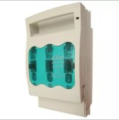
I use these, with NH00 fuses.
 

Attachments

  • EAF19B16-20DC-4471-BF32-534DB643C5DC.jpeg
    EAF19B16-20DC-4471-BF32-534DB643C5DC.jpeg
    185.8 KB · Views: 21
I use these mounted on the positive BusBar for branch circuits. All the engineers I have read or talked recommend ClassT fuses for main fuse on LiPo battery banks. I have recently learned there are multiple physical sizes of classT fuses and holders.
 
Any thoughts on why I would want the redundant fusing in my system?

Unless there is anything else between the battery fuse and inverter fuse (eg: charge source), you only need one fuse between the battery and the inverter - as close to the battery as practical.

If you have a bus bar between your battery and inverter, anything that connects to that needs its own fuse.
 
  • Like
Reactions: Dzl
Any thoughts on why I would want the redundant fusing in my system?
Can you post the victron schematic you are referring to, it would be helpful to see the full example system to understand why they are using two.
 
There are a couple marine centric design considerations that might account for the layout of that diagram.
One possible reason, I believe its common for boats to have considerably large DC loads, I can't remember what specificically (bow thrusters?). So a main fuse located close to the battery (ABYC marine standards say within 7" I believe but don't quote me), that is large enough to handle the theoretical max AC + DC loads might make sense, and that fuse might be too large to protect the inverter or inverter circuit on its own.

It also may just be that the change in wire size in that specific diagram (from the batteries to main busbars, and then the main busbars to inverter) called for a smaller fuse to protect the smaller wire.

In any case, setting that diagram aside, if your situation is such that (1) the main fuse can be located near the battery bank, and (2) you can size the fuse large enough to use as a main fuse (handle all AC and DC loads), and small enough to protect the inverter circuit, I think you could safely just use the one (its a common approach).
 
In any case, setting that diagram aside, if your situation is such that (1) the main fuse can be located near the battery bank, and (2) you can size the fuse large enough to use as a main fuse (handle all AC and DC loads), and small enough to protect the inverter circuit, I think you could safely just use the one (its a common approach).
Perfect, that's what I was thinking.

I'm pretty sure Victron is recommending a 300A fuse on the MultiPlus 24/3000/70 because peak power would be (6000/24), sized up to 125%. I'll use AWG 1/0 wire from the battery through to the inverter and have no concerns.

Thanks for that very clearly worded answer.

A.
 
  • Like
Reactions: Dzl
"Redundant" fuses allows disconnect and or protection of one circuit while the other circuits stay live. ie; Inverter 200A fuse can blow while the battery 250 amp fuse keeps the charger going and the fridge keeps the beer cold.
 
"Redundant" fuses allows disconnect and or protection of one circuit while the other circuits stay live. ie; Inverter 200A fuse can blow while the battery 250 amp fuse keeps the charger going and the fridge keeps the beer cold.
Well said, thank you for the post.

Considering the very short conductor distances, the protection piece probably doesn't make much difference. But the disconnect ability would be very useful.

A.
 
Well said, thank you for the post.

Considering the very short conductor distances, the protection piece probably doesn't make much difference. But the disconnect ability would be very useful.

A.
An important benefit of the typical feeder + branch circuits architecture as implemented with fused positive busbar and an un-fused negative busbar is fault isolation to a single branch.
Works the same if the branch circuits are 10 feet round trip or 10 inches round trip.
 
An important benefit of the typical feeder + branch circuits architecture as implemented with fused positive busbar and an un-fused negative busbar is fault isolation to a single branch.
Works the same if the branch circuits are 10 feet round trip or 10 inches round trip.
In my system, the Class-T on the battery is connected to essentially the same stud as the positive conductor going to the inverter. So adding a class-t would put two of them directly inline with each other. Which would blow if there was a short circuit between the second fuse and the inverter?

All my other DC loads are fed with an 80A MCB.

A.
As the architect of your system that is your prerogative.
For nearly everything I draw I use one or more feeder circuits with class-t fuse as close as possible to the battery.
For the branches I like mrbf or mega fuses at the start of the branch to hopefully isolate a fault to the branch.
If the branch fuse can't quench the arc then the class-t hopefully will prevent catastrophe.
The further away from the battery, the higher the path resistance which means less current into a dead short.
 
More than one way to skin a cat:


For a 3000W inverter on 24V, I think 200A or higher is sufficient.
 
two fuses inline? the smaller ampere rated fuse would go first. i see no advantage to having two fuses in line that are the same amperes.
 
Back
Top