diy solar

diy solar

Fuses/breakers & Safety

tonyg

New Member
Joined
Apr 5, 2022
Messages
136
Hello DIYers!

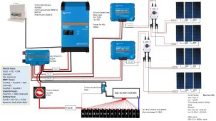
I've finalised my Victron order, have the solar panels and looking to get all the fuses, breakers, etc in place for the safety of the system.

Can anyone with more experience have a look and tell me please if my fuse calculations and positions are good? Any other breakers, fuses, etc to add?

Thank you very much for checking my post!

Edit: Added a PDF with higher resolution that could be checked better.
 

Attachments

  • system-design-with-fuses.jpg
    system-design-with-fuses.jpg
    180 KB · Views: 54
  • system-design-with-fuses.pdf
    642.3 KB · Views: 23
As long as the fuse value is less than 115% of wire ratings at 105*C AND 15% more than the max current you should be in good shape.

IMHO oversizing solar cables and using battery cables 1 or 2 sizes bigger than math/tables require is an optional thing to do; but I fuse as if it were the smaller/correct gage cable.
They’ll never get hot. This has an advantage of not needing to buy more cabling if you upgrade to something needing more capacity, but things stay cooler when you use it hard. An element of safety and a whisper of efficiency gained (heat is lost energy)
None of that is required and using the correct sizes is not unsafe but the relative cost to oversize isn’t usually a big deal.
 
Thank you! I have not yet computed the wire sizes, I have computed the fuses based on the appliances used. Wire sizes would be next step.
 
8000 ac volts amps ~= 6400 ac watts
6400 ac watts / .85 conversion factor / 48 volts low cutoff = 156.862745098 service amps
156.862745098 service amps / .8 fuse headroom = 196.078431373 fault amps

That means 70mm2 with 300 amp class -t fuse as close to battery positive as possible
Connect the battery circuit to the left side of the power-in

70mm2 with 250 amp mega fuse for inverter branch.

MPPT wires should be 16mm2 with 100 amp mega fuse.
The solar charge controller has output short circuit protection so the branch fuse just has to protect the wire

Use the explorist life method to fuse each branch circuit.

Your drawing doesn't show any bond to the dirt.
Your drawing doesn't show any wire sizes.
Daly BMS has very little balancing capacity.

q: Why 4 strings of panels instead of 1 or 2 higher voltage strings?
 
Last edited:
Why 4 strings of panels instead of 1 or 2 higher voltage strings?
Obviously I’m not him but his VOC is like 123V and the controllers are 150V maybe?
Unless I read it wrong on my phone
Your drawing doesn't show any bond to the dirt.
for a purely offgrid setup it may not be needed, would it? Dirt is not naturally or inherently part of the circuit diagram.
 
8000 ac volts amps ~= 6400 ac watts
6400 ac watts / .85 conversion factor / 48 volts low cutoff = 156.862745098 service amps
156.862745098 service amps / .8 fuse headroom = 196.078431373 fault amps

That means 70mm2 with 300 amp class -t fuse as close to battery positive as possible
Connect these to the left side of the power-in

70mm2 with 250 amp mega fuse for inverter branch.

MPPT wires should be 16mm2 with 100 amp mega fuse.
The solar charge controller has output short circuit protection so the branch fuse just has to protect the wire

Use the explorist life method to fuse each branch circuit.

Your drawing doesn't show any bond to the dirt.
Your drawing doesn't show any wire sizes.
Daly BMS has very little balancing capacity.

q: why 5 strings of panels instead of 1 or 2 higher voltage strings?
Brilliant, lots to do indeed. I was going to research and add grounding a bit later - surely before mounting the system, but I'm doing baby steps, little by little. Initial thought is grounding to be added to the frames of the panels, and then I'll check if the inverted needs it too.

I'll start with the last question: shading problems have pushed me with this solution of two MPPTs. Six of the panels will be shaded in the morning and evening, and three from those six will be shaded even more than the other three, hence two parallel strings. I've had a thread discussing this as well and it seems like an optimal solution for best harvest of energy. The price difference between having one large mppt or two smaller ones was not big.

Regarding the Daly BMS, it is easily accessible here in the UK and allows plenty of power (250A). I thought for LifePo4, one would do an initial balance, and then they would work without need to be ballanced again for a while at least. Happy to change this, I haven't bought the BMS or batteries yet.

With regards to the battery fuse, I based that on max current allowed by Daly (250A), thus 250 x 1.25 = 312.5 A, hence going for the 320A, why would that be too much? You've suggested 300A one.

The inverter fuse is a 300A one based on the manual of the Victron Multiplus-II 48/8000, page 13 , Recommended DC fuse.
Similarly, the 60A fuses are also based on the manual of the Smartsolars 150/45.
Why only 250A fuse for the inverter, and why such a large, 100A fuse for MPPTs?

I'm not in any way arguing, just trying to understand your advice better and take the best decision in the end.

Thank you!
 
8000 ac volts amps ~= 6400 ac watts
6400 ac watts / .85 conversion factor / 48 volts low cutoff = 156.862745098 service amps
156.862745098 service amps / .8 fuse headroom = 196.078431373 fault amps

That means 70mm2 with 300 amp class -t fuse as close to battery positive as possible
Connect the battery circuit to the left side of the power-in

70mm2 with 250 amp mega fuse for inverter branch.

MPPT wires should be 16mm2 with 100 amp mega fuse.
The solar charge controller has output short circuit protection so the branch fuse just has to protect the wire

Use the explorist life method to fuse each branch circuit.

Your drawing doesn't show any bond to the dirt.
Your drawing doesn't show any wire sizes.
Daly BMS has very little balancing capacity.

q: Why 4 strings of panels instead of 1 or 2 higher voltage strings?
That video is very good, and I'll use the power in that way certainly.

Thank you very much!
 
I'll start with the last question: shading problems have pushed me with this solution of two MPPTs. Six of the panels will be shaded in the morning and evening, and three from those six will be shaded even more than the other three, hence two parallel strings. I've had a thread discussing this as well and it seems like an optimal solution for best harvest of energy. The price difference between having one large mppt or two smaller ones was not big.
These scc's have multiple trackers.
Do you need 2 scc or or do you need 4 strings?

Regarding the Daly BMS, it is easily accessible here in the UK and allows plenty of power (250A). I thought for LifePo4, one would do an initial balance, and then they would work without need to be ballanced again for a while at least. Happy to change this, I haven't bought the BMS or batteries yet.
Depends on the quality and match of the cells.
Almost all cells are called grade A by the broker.
Its my opinion that the only grade A cells come through the broker channels are basically order filler.
In other words that means that the manufacuturer didn't have enough non grade A cells on hand to complete the broker order.
Unless you bought your cells direct from the manufacturer expect them to be less than grade A.
With regards to the battery fuse, I based that on max current allowed by Daly (250A), thus 250 x 1.25 = 312.5 A, hence going for the 320A, why would that be too much? You've suggested 300A one.
The fuse is based on the wire size and all the in-line components of the main circuit.
300 amps is largest fuse that should be used with 70mm2.
Why only 250A fuse for the inverter, and why such a large, 100A fuse for MPPTs?
The inverter circuit should be the next size down for fault isolation.
In other words we give the inverter branch circuit fuse a chance to blow before the main fuse.
This way the rest of the system can still function.
Again we fuse for the wire as the victron inverter and mppt units have their own internal short circuit protection.
The larger the wire the smaller the voltage drop.
Since freshly squeezed diy electricity is so expensive I hate to waste it due to voltage drop.

Hope this is all clear.
If not, please don't hesitate to follow up.
 
Last edited:
These scc's have multiple trackers.
Do you need 2 scc or or do you need 4 strings?
I need 4 separate strings in my case. I've raised this in a thread, here:
https://diysolarforum.com/threads/i...than-having-one-bigger-mppt.38383/post-485955

Depends on the quality and match of the cells.
Almost all cells are called grade A by the broker.
Its my opinion that the only grade A cells come through the broker channels are basically order filler.
In other words that means that the manufacuturer didn't have enough non grade A cells on hand to complete the broker order.
Unless you bought your cells direct from the manufacturer expect them to be less than grade A.
Someone is waiting for a shipment from China and I'll buy from them. They say class A, and I trust it's that way.
The fuse is based on the wire size and all the in-line components of the main circuit.
300 amps is largest fuse that should be used with 70mm2.

The inverter circuit should be the next size down for fault isolation.
In other words we give the inverter branch circuit fuse a chance to blow before the main fuse.
This way the rest of the system can still function.
I understand. Would going a size larger like 320A for the battery fuse (main fuse) and 300A for the inverter not be advisable? Of course, I would need to size the wires accordingly - but if it is better for other reasons to have weaker fuses, then I can agree to that as well.
Again we fuse for the wire as the victron inverter and mppt units have their own internal short circuit protection.
The larger the wire the smaller the voltage drop.
Since freshly squeezed diy electricity is so expensive I hate to waste it due to voltage drop.
I agree 100%, I am planning to oversize the wires by a bit for this reason.
Hope this is all clear.
If not, please don't hesitate to follow up.
It is getting clearer, thank you again!
 
Someone is waiting for a shipment from China and I'll buy from them. They say class A, and I trust it's that way.
I hope that someone ordered from the manufacturer.
I understand. Would going a size larger like 320A for the battery fuse (main fuse) and 300A for the inverter not be advisable?
Fuse sizes are not very granular.
The largest mega fuse is 300 amps.
Second largest mega fuse is 250 amps.
Class t fuses are 50 amp increments.
I stand by the my original assessment.
Of course, I would need to size the wires accordingly - but if it is better for other reasons to have weaker fuses, then I can agree to that as well.
Lower rated fuses have higher resistance.
The fuses need to protect the wires.
Passive in-line components are considered to be part of the wire.
Your mppt controllers and inverter/charger have their own over-current protection.
 
Last edited:
You don't need to fuse each panel in the string.
You just need to fuse the strings.
 
First thing that caught my eye is the low ampere rating of the battery disconnect switch. Don't switch that under full load.
Fuses are the last to be selected. #1-Determine maximum amperes of device. #2- Determine cable gauge using a voltage drop table. #3- Select the amperes of fuses to match the ampacity of the selected cable. #4- Select the proper type fuse for the interrupt capacity needed by the battery.
#1 #1 Fuses protect wires.
Again, select the needed wire gauge then select the fuse to protect that wire.
 
Let me try this another way.

2/0 awg wire from battery to class -t fuse 330 amps
300 amp class-t fuse, 20,000+ breaking amps
2/0 awg wire from class-t fuse to busbar 330 amps
busbar 1000 amps
250 amp mega fuse, ~2000 breaking amps
2/0 awg wire from busbar to inverter 330 amps
inverter(has its own over-current protection)
2/0 awg wire from inverter to busbar 330 amps
2/0 awg wire from busbar to shunt 330 amps
2/0 wire from shunt to bms 330 amps
bms 250 amps service amps / .8 fuse headroom = 312.5 fault amps, ? breaking amps
2/0 wire from shunt to battery 330 amps.

If there is a fault on the inverter circuit we hope the branch fuse will isolate it.
If not, hopefully the bms will disconnect it.
If not, the class-t fuse is the last line of defense.
 
Last edited:
Let me try this another way.

2/0 awg wire from battery to class -t fuse 330 amps
300 amp class-t fuse, 20,000+ breaking amps
2/0 awg wire from class-t fuse to busbar 330 amps
busbar 1000 amps
250 amp mega fuse, ~2000 breaking amps
2/0 awg wire from busbar to inverter 330 amps
inverter(has its own over-current protection)
2/0 awg wire from inverter to busbar 330 amps
2/0 awg wire from busbar to shunt 330 amps
2/0 wire from shunt to bms 330 amps
bms 250 amps service amps / .8 fuse headroom = 312.5 fault amps, ? breaking amps
2/0 wire from shunt to battery 330 amps.

If there is a fault on the inverter circuit we hope the branch fuse will isolate it.
If not, hopefully the bms will disconnect it.
If not, the class-t fuse is the last line of defense.
Thank you very much @smoothJoey ! Now that is easier to understand, I appreciate your time to do this.

In addition, doing some googling I realised what you have said in an earlier post. There are no fuses with the amperages I wanted and thus I'll have to go with the ones you suggested..

Cheers!
 
First thing that caught my eye is the low ampere rating of the battery disconnect switch. Don't switch that under full load.
Fuses are the last to be selected. #1-Determine maximum amperes of device. #2- Determine cable gauge using a voltage drop table. #3- Select the amperes of fuses to match the ampacity of the selected cable. #4- Select the proper type fuse for the interrupt capacity needed by the battery.
#1 #1 Fuses protect wires.
Again, select the needed wire gauge then select the fuse to protect that wire.
Hi @Zil , I'm a bit confused with your statement above, "#1 #1 fuses protect wires". While they do protect wires, are they not meant first of all to protect the attached devices? One could oversize their wire to minimise voltage drop, then the fuse will be bigger... But then that can result in blowing the attached device, right?
 
Hi @Zil , I'm a bit confused with your statement above, "#1 #1 fuses protect wires". While they do protect wires, are they not meant first of all to protect the attached devices? One could oversize their wire to minimise voltage drop, then the fuse will be bigger... But then that can result in blowing the attached device, right?
I know you asked Zil but I will answer with the understanding that Zil will also answer.

The circuit fuses protect the wire and wire like devices.
By wire like devices, I mean all the in-line passive devices that make the rest of the circuit.
For example busbar, shunt, bms, disconnect switch, battery protect, etc.

The load(appliance) has resistance which is the primary regulator of current flow through the circuit.
The other being voltage.

Lets take an inverter for example.

Any halfway decent inverter has over voltage protection and will shut down the inverter on over-voltage.

Basically there are two ways for the inverter to not regulate current.

1: Internal fault in the appliance.
Any halfway decent inverter has built in over-current protection to protect against this scenario.
The appliance fuse protects the appliance from itself.
It also protects the wire from the appliance.
The circuit fuse protects the wire from the appliance.

2: Short circuit on the wire up-stream of the appliance.
The inverter is not in the circuit in this scenario so it doesn't require protection.

I've used an inverter for example but the same concepts apply to all appliances.
Don't use appliances that don't have built in protections.

To re-iterate the fuse protects the wire and "wire-like" devices.
I highlighted some things in my previous posts that you should look at again after reading this.
 
Last edited:
@tonyg have I convinced you?
Yes you did, it makes much more sense now, thank you very much.

I will redo the schematics with the wire sizes you suggested and fuses as well - the sizes are jumping from 50 to 50 as you said, it's not easy or better said it is impossible having a mega fuse of 320.

Thanks again you were most kind to take your time and help with this.
 
Yes you did, it makes much more sense now, thank you very much.
I meant about the circuit fuse not protecting the appliance.
I think its common for intuition to get in the way of understanding on this one.
 
  • Like
Reactions: Zil
Back
Top