First of all I would like to thank @WillProwse for this forum and all of the wonderful members. I could not have made it this far without your help and I still have a ways to go, but I am getting there.
Second I would like to thank @AussieSim for his review of his Snadi which prompted me to look into the company.
Third I would like to thank @Michael B Caro for the great deal on the 8 EVE 280ah cells.
Finally, I would like to thank my Snadi contact, Camille. She was very helpful answering my questions. The language barrier can be frustrating at times but we made it.
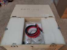
Camille included battery cables and they are not the best, but good enough to get started and for some testing. I think they are 4AWG but they have large wire strands. I had to cut the lugs off of one end and strip the insulation so I could insert the wires into the Din Rail Terminals. I will be replacing the cables.
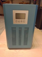
All of Snadi's products come in different flavors. And some can be customized. I chose a 2000 watt, 24 volt DC, 110 volt AC 60hz UPS.
Link to Snadi's Alibaba website:

 snadi.en.alibaba.com
1-21-21 Total paid including DHL Air and CC fee: $415.92
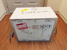
2-10-2021 Received Snadi on time in good condition. It arrived in a plywood box.
Discharging:
2-11-2021 The unit came with Grid Priority Mode set as the default. The default battery setting was set to U1 A.G.M.1 26.8 Volts. I have started to discharge the pack using the Snadi with the power disconnected from the grid. Average load is 375 watts.
2-12-2021 I have continued discharging the pack to see if the Snadi will shut down before the BMS hits LVD. It did not.
Capacity dropped one bar on the Snadi display when the voltage dropped to 25.03 volts, next bar 24.30, next bar 23.58. I shut the Snadi off shortly before the BMS LVD would have kicked in.
Charging:
2-12-2021 I let the battery pack rest for around an hour then started charging. Then I plugged in my loads. The max charge current of this Snadi 24 volt model is 15-20 amps and current does fluctuate a bit when charging or discharging. I am currently using the U2 A.G.M.2, 27.40 Volt setting.
2-13-2021 The voltage exceeded 27.40 volts and the Snadi display stopped indicating a charge at 27.65 volts. The current tapered off when 27.65 volts was reached. The voltage of the pack is being held at 27.68 volts. I know the float voltage is too high. Charging can be shut off but I discovered the UPS draws 300ma's even with charging shut off.
NOTE: The AGM1 setting of 26.8 volts is best for this application using LFE cells. It still goes over the 26.8 volt pre set voltage. The end of the charge is 27.07 volts and that's where it floats. I have been able to balance my cells so the highest cell floats at 3.390 volts.
Charging Profile Tests:
U0: GEL U.S.A, 27.4 Volts: Did not test. Same voltage as U2.
U1: AGM1, 26.8 Volts: Charged to 27.07 volts and the Snadi floated at that voltage.
U2: AGM 2, 27.4 Volts: Charged to 27.68 volts and the Snadi floated at that voltage.
U3: SEALED LEAD ACID, 27.2 Volts : Charged to 27.49 volts and the Snadi floated at that voltage.
U4: GEL EUROPEAN, 27.6 Volts: Did not test. Same voltage as U5.
U5: OPEN LEAD ACID, 27.6 Volts: Charged to 27.85 volts and the Snadi floated at that voltage.
U6 CALCIUM: 27.2 Volts: Did not test. Same voltage as U3.
U7: DESULPHATION: 31 Volts: Not to be used with LFE cells.
NOTE: My meter did not detect any AC ripple at the battery terminals while charging.
Inverter AC Output No Load. L=Line, N=Neutral, G=Ground :
LN = 108.6 Volts LG = 85 Volts NG = 18 Volts
Inverter AC Output 150 Watt Load:
LN = 109.7 LG = 62 Volts NG = 47 Volts.
Testing inverter AC Output using 850 Watt Load:
LN = 109.6 LG = 62 Volts NG = 47 Volts.
Ambient Temp: 73F All temps measured at highest readings. I checked temps several times.
Temp of UPS fan output: 79
Temp of DC Din Terminal - UPS Battery Input: 79
Temp of BMS cables: 83.7
Temp of fuse: 83.3
Temp of Snadi's AC outlet: 74.1
Inverter pulling 32.8 to 33.6 amps from battery. This fluctuates.
Voltage delta of cells. It fluctuates .011 - .026
I measured the AC output with a volt meter while connected to the grid and the AC output is around 1 volt less than the AC input with the inverter charging at 15 amps and an 850 watt load.
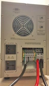
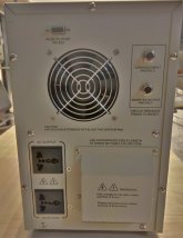
NOTE: The AC outlets installed in the UPS are rated for 10 amps or apx. 1100 watts. The UPS hard wiring input is rated for apx. 16.7 amps or 2000 watts with a 120 volt input. This slightly exceeds the output of a standard AC outlet in the US. If using a standard AC outlet I would not run the UPS much over 1500 watts. If it is hard wired into an electrical panel then it should be able to run at 2000 watts continuously. As soon as I can hard wire a power strip or something to the AC output of the UPS, I will proceed to test using a higher load than I did this test. That could be a while but I wanted to post my conclusions so far.
Likes:
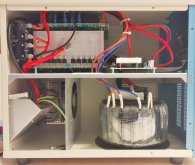
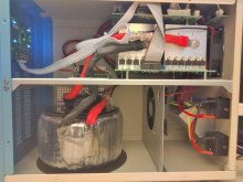
1: The unit is very sturdy and the interior wiring looks good to me. It's not a Samlex or Victron but so far I like it.
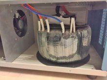
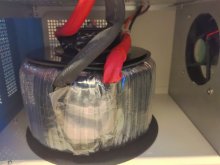
2: Most of the Snadi's use a toroidal transformer. There are several advantages and disadvantages with this type of transformer. It's my understanding one of the benefits is they are more efficient.
3: The inverter idle load varies between 14 and 17 watts.
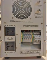
4: Easy to install the battery cables even though the unit uses Din Rail terminals.
5: Wiring the AC input was easy. I haven't wired the AC output yet but I intend to. I want to get the most power I can out of the unit mainly for testing. The UPS does supply 10 amps out of the outlets on the back which is equal to 1100 watts. Using the hard wiring of the AC output the Snadi would be limited to a total of 1800 watts which is the total the common USA outlet can supply.
6: The UPS function works great. I don't have a scope but I plugged in an old dell laptop that has no battery and when I unplugged power from the grid it didn't blink. My 55" TV doesn't blink either. So the transfer time is good.
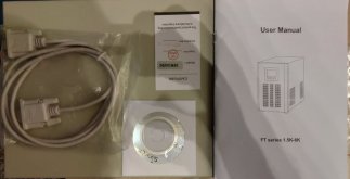
7: The monitoring software came on an included CD. It does report the temperature of the Snadi and has a bar graph to indicate the load. Unfortunately it does not report the wattage. At least I know the serial port works which I paid an extra $5.00 for. I believe the software was compiled in 1999. It does work fine on Windows 10 and works with a serial to USB adapter.
Dislikes:
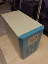
1: One case panel wasn't lined up quite right. Had to force it to get it right.
2: The top panel doesn't line up quite right with the front of the case but this is nit picking.
3: The charging profiles work but once the set voltage is reached the Snadi floats at the set charge voltage and the end of charge voltage is always a bit higher than listed in the manual.
4: I discovered the Snadi is drawing 300ma's from the battery with charging shut off.
Conclusion:
This is a very basic UPS. There are no adjustments for LVD or HVD, absorb, float or anything else other than the battery types I listed above and the charging current. For my needs it's fine and so far I feel I got my moneys worth. I know distributers can request to have firmware loaded to allow for various advanced settings. Unfortunately Camille told me they could not do this for a single order. The biggest plus of this type of UPS is the ability to add your own battery pack. Based on my experience so far I do recommend Snadi.
Support:
The only problem I am having is with the charge current. Camille told me this Snadi UPS charges in 3 stages and should charge with at least 25 amps of current. The manual indicates 30 amps. The highest charge current I have noticed is around 20 amps when I start charging my battery. But it quickly tapers off to 17.5 amps.
Camille has been working with me on this and I will report back with the outcome. She has not ignored any of my questions and we are still trying to figure out why this is happening. Personally I think it's could be a misprint in the manual.
I wasn't able to remove the top of the UPS. It's tucked in tight. I may try later.
Second I would like to thank @AussieSim for his review of his Snadi which prompted me to look into the company.
Third I would like to thank @Michael B Caro for the great deal on the 8 EVE 280ah cells.
Finally, I would like to thank my Snadi contact, Camille. She was very helpful answering my questions. The language barrier can be frustrating at times but we made it.
Camille included battery cables and they are not the best, but good enough to get started and for some testing. I think they are 4AWG but they have large wire strands. I had to cut the lugs off of one end and strip the insulation so I could insert the wires into the Din Rail Terminals. I will be replacing the cables.
All of Snadi's products come in different flavors. And some can be customized. I chose a 2000 watt, 24 volt DC, 110 volt AC 60hz UPS.
Link to Snadi's Alibaba website:
Foshan Snat Energy Electrical Technology Co., Ltd.
Foshan Snat Energy Electrical Technology Co., Ltd., Experts in Manufacturing and Exporting and 0 more Products.
1-21-21 Total paid including DHL Air and CC fee: $415.92
2-10-2021 Received Snadi on time in good condition. It arrived in a plywood box.
Discharging:
2-11-2021 The unit came with Grid Priority Mode set as the default. The default battery setting was set to U1 A.G.M.1 26.8 Volts. I have started to discharge the pack using the Snadi with the power disconnected from the grid. Average load is 375 watts.
2-12-2021 I have continued discharging the pack to see if the Snadi will shut down before the BMS hits LVD. It did not.
Capacity dropped one bar on the Snadi display when the voltage dropped to 25.03 volts, next bar 24.30, next bar 23.58. I shut the Snadi off shortly before the BMS LVD would have kicked in.
Charging:
2-12-2021 I let the battery pack rest for around an hour then started charging. Then I plugged in my loads. The max charge current of this Snadi 24 volt model is 15-20 amps and current does fluctuate a bit when charging or discharging. I am currently using the U2 A.G.M.2, 27.40 Volt setting.
2-13-2021 The voltage exceeded 27.40 volts and the Snadi display stopped indicating a charge at 27.65 volts. The current tapered off when 27.65 volts was reached. The voltage of the pack is being held at 27.68 volts. I know the float voltage is too high. Charging can be shut off but I discovered the UPS draws 300ma's even with charging shut off.
NOTE: The AGM1 setting of 26.8 volts is best for this application using LFE cells. It still goes over the 26.8 volt pre set voltage. The end of the charge is 27.07 volts and that's where it floats. I have been able to balance my cells so the highest cell floats at 3.390 volts.
Charging Profile Tests:
U0: GEL U.S.A, 27.4 Volts: Did not test. Same voltage as U2.
U1: AGM1, 26.8 Volts: Charged to 27.07 volts and the Snadi floated at that voltage.
U2: AGM 2, 27.4 Volts: Charged to 27.68 volts and the Snadi floated at that voltage.
U3: SEALED LEAD ACID, 27.2 Volts : Charged to 27.49 volts and the Snadi floated at that voltage.
U4: GEL EUROPEAN, 27.6 Volts: Did not test. Same voltage as U5.
U5: OPEN LEAD ACID, 27.6 Volts: Charged to 27.85 volts and the Snadi floated at that voltage.
U6 CALCIUM: 27.2 Volts: Did not test. Same voltage as U3.
U7: DESULPHATION: 31 Volts: Not to be used with LFE cells.
NOTE: My meter did not detect any AC ripple at the battery terminals while charging.
Inverter AC Output No Load. L=Line, N=Neutral, G=Ground :
LN = 108.6 Volts LG = 85 Volts NG = 18 Volts
Inverter AC Output 150 Watt Load:
LN = 109.7 LG = 62 Volts NG = 47 Volts.
Testing inverter AC Output using 850 Watt Load:
LN = 109.6 LG = 62 Volts NG = 47 Volts.
Ambient Temp: 73F All temps measured at highest readings. I checked temps several times.
Temp of UPS fan output: 79
Temp of DC Din Terminal - UPS Battery Input: 79
Temp of BMS cables: 83.7
Temp of fuse: 83.3
Temp of Snadi's AC outlet: 74.1
Inverter pulling 32.8 to 33.6 amps from battery. This fluctuates.
Voltage delta of cells. It fluctuates .011 - .026
I measured the AC output with a volt meter while connected to the grid and the AC output is around 1 volt less than the AC input with the inverter charging at 15 amps and an 850 watt load.
NOTE: The AC outlets installed in the UPS are rated for 10 amps or apx. 1100 watts. The UPS hard wiring input is rated for apx. 16.7 amps or 2000 watts with a 120 volt input. This slightly exceeds the output of a standard AC outlet in the US. If using a standard AC outlet I would not run the UPS much over 1500 watts. If it is hard wired into an electrical panel then it should be able to run at 2000 watts continuously. As soon as I can hard wire a power strip or something to the AC output of the UPS, I will proceed to test using a higher load than I did this test. That could be a while but I wanted to post my conclusions so far.
Likes:
1: The unit is very sturdy and the interior wiring looks good to me. It's not a Samlex or Victron but so far I like it.
2: Most of the Snadi's use a toroidal transformer. There are several advantages and disadvantages with this type of transformer. It's my understanding one of the benefits is they are more efficient.
3: The inverter idle load varies between 14 and 17 watts.
4: Easy to install the battery cables even though the unit uses Din Rail terminals.
5: Wiring the AC input was easy. I haven't wired the AC output yet but I intend to. I want to get the most power I can out of the unit mainly for testing. The UPS does supply 10 amps out of the outlets on the back which is equal to 1100 watts. Using the hard wiring of the AC output the Snadi would be limited to a total of 1800 watts which is the total the common USA outlet can supply.
6: The UPS function works great. I don't have a scope but I plugged in an old dell laptop that has no battery and when I unplugged power from the grid it didn't blink. My 55" TV doesn't blink either. So the transfer time is good.
7: The monitoring software came on an included CD. It does report the temperature of the Snadi and has a bar graph to indicate the load. Unfortunately it does not report the wattage. At least I know the serial port works which I paid an extra $5.00 for. I believe the software was compiled in 1999. It does work fine on Windows 10 and works with a serial to USB adapter.
Dislikes:
1: One case panel wasn't lined up quite right. Had to force it to get it right.
2: The top panel doesn't line up quite right with the front of the case but this is nit picking.
3: The charging profiles work but once the set voltage is reached the Snadi floats at the set charge voltage and the end of charge voltage is always a bit higher than listed in the manual.
4: I discovered the Snadi is drawing 300ma's from the battery with charging shut off.
Conclusion:
This is a very basic UPS. There are no adjustments for LVD or HVD, absorb, float or anything else other than the battery types I listed above and the charging current. For my needs it's fine and so far I feel I got my moneys worth. I know distributers can request to have firmware loaded to allow for various advanced settings. Unfortunately Camille told me they could not do this for a single order. The biggest plus of this type of UPS is the ability to add your own battery pack. Based on my experience so far I do recommend Snadi.
Support:
The only problem I am having is with the charge current. Camille told me this Snadi UPS charges in 3 stages and should charge with at least 25 amps of current. The manual indicates 30 amps. The highest charge current I have noticed is around 20 amps when I start charging my battery. But it quickly tapers off to 17.5 amps.
Camille has been working with me on this and I will report back with the outcome. She has not ignored any of my questions and we are still trying to figure out why this is happening. Personally I think it's could be a misprint in the manual.
I wasn't able to remove the top of the UPS. It's tucked in tight. I may try later.
Attachments
Last edited: