diy solar

diy solar

Generator to Growatt Inverter Neutral Bonding - Arg

Joe BoyKey

Watts, Watts, more Watts
Joined
Sep 11, 2020
Messages
534
Location
Austin Texas
Ok, searched and read 10+ post here and numerous post elsewhere, got a solid answer from BB @ Northern Arizona Wind & Sun Solar Forum - THANKS
Just need peace of mind, not get electrocuted and mostly not FRY my inverter, thanks in advance, Joe.
Items involved:
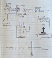
1. Growatt SPF-6000T-DVM - Low frequency split phase 6kw 240v Inverter charge controller - feeding Garage
2. Westinghouse WGen7500DF Generator - 240v 30a L14-30r plug, won't be using 120v ground fault outlets ever!
See pic, Generator ships with "neutral bonded to FRAME", Growatt only requires L1 L2 and Ground, no neutral,
Growatt takes L1 L2 and ground and makes its own neutral (70lbs transformer), neutral is bonded to ground in the House breaker box. (all as is now)
Want to add a breaker to 6 position breaker panel in pic with lockout for Utility or Generator manual transfer - Generator outside -
jumper cable from L14-30r to wall mounted Receptacle hard wired to Growatt sub-panel.
Questions:
1. L1 L2 to Breaker, ground to ground, no neutral - is this correct?
2. was told to leave neutral bonded to FRAME on generator - is this correct?
3. do i ground the generator frame to ANYTHING? - only ground other than House grond at house panel is Solar panels???
Sorry for the same question over again, just not a trailer or boat and no transfer switch - just having trouble with "1 single Neutral to Ground period"
If breaker to Growatt is off, grounds still bonded, and the breaker from Generator is on - where is the potential to flip breaker in case of short/overload?

1614003023514.png

1614003001975.png
 
I am also very interested in this - your proposed setup is very similar to what I am planning.

I am absolutely not an expert, but here are my thoughts. Would very much like to hear more expert advice:

q1: the 6000t manual says 240 in, which I also assume would be done via L1 and L2 from the 240subpanel, plus ground, as you have shown.

q2 - Your diagram appears to be missing a line from your main breaker box to your sub breaker box - there should be the two live legs, neutral and ground. in additional the connection from the generator to the sub breaker box will also have 4 wires. The neutral and ground will link to the neutral and ground in the sub-breaker box. The breaker in the sub box will switch L1 and L2 between generator and main panel, but not neutral or ground. Therefore if the generator has a bonded neutral there will be two bonds - one in the main breaker box, and one in the generator. Not good - I would remove the bond in the generator - it should only be there if the generator is on a completely independent circuit from the house.

Q3. as long as you wire the ground from the generator into the sub panel it will be grounded.

Where it gets really interesting is your comment “Growatt takes L1 L2 and ground and makes its own neutral (70lbs transformer), neutral is bonded to ground in the House breaker box. (all as is now)”. Does this mean that the output neutral from the GroWatt is linked to the sub breaker box and main breaker box neutral? There are a few threads where people create circuits that bond the neutral to the ground near the GroWatt when in inverter mode, but remove the bond when in utility mode. I am not clear on whether this is necessary, or if it would be possible to have one common neutral for all the breaker boxes, the GroWatt, and the generator.

looking forward to illumination! (But not in a “fire” kind of way.....)
 
Does this mean that the output neutral from the GroWatt is linked to the sub breaker box and main breaker box neutral?
NO, Neutral from Growatt is floating and feeding the Breaker box - feeding dedicated Garage circuits. Where would neutral hook too,
not Growatt as seen below no neutral input, Neutral out - split phase feeds a separate panel isolated from house except for ground.
Everything in the second pic shares a common ground from house panel, which is bonded to Neutral there. Panels = separate ground.

That's why I posted here for expert info, got this from a expert on another site, i' still confused due to the fact that -
"netral can be bonded to ground only in 1 place" Also bonded neutral on the gen is for the Ground fault 120v receptacles????
That's the mail question - remove or leave gen bonding? Generator arrives tomorrow, tempted to just power Garage instead of Growatt
and let the sun keep the batteries charges - in an emergency, In Austin, Tx - never lost power or water last week, ERCOT 2.5 mile away!!!!

From Bill:
Interesting... Then your "protected" 120/240 subpanel from the inverter will have a neutral+ground bond? It' floating
If your genset is only connected to the GrowWatt AC genset 240 VAC input--Then you really do not need (or want?) to lift the neutral/ground bond inside the genset. L1+L2 still should be "ground referenced" via the internal neutral+ground connection (if L1 or L2 is shorted to ground, you want to trip the genset breakers).
There is no "neutral current" between the genset and load (AC inverter genset input). So no neutral+ground parallel current flow from loads).
1614107828578.png
1614108377736.png
 
Interesting! As you say, if the GroWatt/genset/garage box have a separate neutral (per your diagram) then bonding at the genset works, without conflict.

however, my thought was to have a common neutral for the complete system - I.e. run a neutral from the sub-box to the garage box.

like you say, I would love to have a professional opinion on that....
 
My thought also, with no neutral from the house genset would be the 1 neutral bonding to ground, problem solved.
Waiting to hear from Growatt, Ian passed this off to Victor Zhang to Engineers, awesome support from all of them.
Will keep you posted thanks.

This is what's in the manual for the Gen:
1614126328790.png
 
Update - It works perfect, bit the bullet and replaced new #6 - 3 conductor from house panel with another new #6 - 4 conductor, REMOVED NEUTRAL TO GROUND BONDING on Gen and wired it exactly like Watts247 schematic said to but without transfer switch. Using Back fed breakers so single point neutral to ground is at House panel and never gets removed, see updated pic, will be grounding Gen frame to separate Rod, thanks for Everyone's help, Joe.
src


1615291418302.png
 
Update - It works perfect, bit the bullet and replaced new #6 - 3 conductor from house panel with another new #6 - 4 conductor, REMOVED NEUTRAL TO GROUND BONDING on Gen and wired it exactly like Watts247 schematic said to but without transfer switch. Using Back fed breakers so single point neutral to ground is at House panel and never gets removed, see updated pic, will be grounding Gen frame to separate Rod, thanks for Everyone's help, Joe.
src


View attachment 40182
For reference, look at setting #24 in the video. https://diysolarforum.com/threads/t...eturn-with-grid-tie-growatt.19702/post-230159
 
Update - It works perfect, bit the bullet and replaced new #6 - 3 conductor from house panel with another new #6 - 4 conductor, REMOVED NEUTRAL TO GROUND BONDING on Gen and wired it exactly like Watts247 schematic said to but without transfer switch. Using Back fed breakers so single point neutral to ground is at House panel and never gets removed, see updated pic, will be grounding Gen frame to separate Rod, thanks for Everyone's help, Joe.
src


View attachment 40182
I have done the same - works well!
 
The whole point of having ground to one point and one point only is to prevent circulating currents. Circulating currents will cause nuisance tripping of GFCI’s, for a proper installation that fits your situation is to remove the ground bond at the generator, bring the ground wire to the main distribution panel and from there to the ufer ground or the ground rod,
whichever system that you are using. If you want to power your house with the generator alone without the growatt you will need to bring 4 wires from the generator to the panel. Two hots, neutral, and ground. The neutral does not extend to the growatt. It’s feed wires are L1, L2 and ground. What happens if you have a lightning strike that takes out the growatt.......if you don’t bring the neutral from the generator to the distribution panel then you will not be able to run on generator alone without the growatt operational.

Ufer ground......using the bonded rebar in a foundation as the system ground, typically this is about 10 times better than a single ground rod, it is very popular over here on the left coast.....named for Ufer, the building inspector who invented it
Thanks for the info, in My case loosing the Growatt would only require bypassing it during repairs, wish I had access to rebar in the foundation, haven't dug around foundation except once to fix copper pipe feeding water into house and never saw any rebar protruding from slab. Googled and it looks like it's done during construction. I'm only feeding dedicated circuit in my Garage - seperate from House, in case of power outage it's already powering big Freezer, then only run extension cord to Refrigerator and tv in house. Joe..
 
JoeBoyKey, yes Ufer ground is built in at build time, most houses built here are Ufer ground, not all areas accept Ufer ground, you really can’t add Ufer ground to a existing foundation, it requires bonding of a certain length of rebar, probably 20 feet or so, this I’d determined at the planning stage before the build. The impedance of the ground is different everywhere and is determined by the site engineer or often the building/planning dept. will know what they want there, so no Ufer ground lets move on.....so there should be a copper coated ground rod directly below your main panel with a 6 ga. bare wire In conduit or not in conduit (either is legal) going up to the main panel. Carefully go into the main panel and there should be a ground buss in the panel. If this is the main box with the meter the ground buss and the neutral busses can be combined here...(only in the main box, not in a subpanel) if I understand this right, the solar and inverter only runs the referigerator in the garage ?

Ground rods, Rereading, your solar panels have a separate ground .....that’s a no-no in the National Electric code....correct that by stating that this is a lightning protector then run a 6 ga copper wire from one ground rod to the other ground rod, preferably in a trench buried, bare wire, in any case do not bring it into your house, or through your house. Solar panels are great lightening attractors and you do not want it coming inside with you. The wire should not have any sharp bends, nothing sharper than 8” radii, lightning will jump off a sharp bend and go where?...anywhere it wants, nice easy bends directly to the ground rod.....did you bond your solar panels together? Also required in the NEC, 6 ga copper from panel to panel end to end then to lightning suppressor rod. It gets sticky if you call it a ground rod. It all depends oh your AHJ......."..who it that...it’s the building inspector assuming he knows anything about it. Even if you do not get a permit do everything to the NEC if the worst happens you are way better off. I have to deal with this all the time......the backup battery system that I posted “200 amp pouch cells” I got that for free from a failed installation because the homeowner did not know the right data before purchase and the contractor did not catch the mistake. Oops there went 5K.....purchase and costs to install and remove. It’s way late and I’m tired...if you have any more questions do post. I’d like to see a successful install here....
 
Interesting thread, thanks guys. I just purchased a 6500W generator to use as backup input to my SPF 6000T, and want to make sure I get this right.

I am 100% off-grid. I have a brand new breaker panel on the house and the only input to the panel are the L1, L2, N from the Growatt. The Growatt and house panel circuits are all connected to a common ground rod. The house neutral and ground are not connected. This system is working great. I have two 240V mini-split air conditioners, each on their own 240V dual-pole breaker in the panel. The rest of the breakers in the panel are 20A 120V powering the rest of the circuits in the house.

I have a standard 30A generator input box that I plan to install on the outside of my battery/control room, and then connect the generator via a standard 4-prong generator extention cord. The generator has neutral bonded to ground with ability to disconnect that. I plan to run the L1 and L2 inputs to the Growatt through a dual-pole breaker.

Q1) Do I only run L1 and L2 and G from the generator input box to the Growatt? and leave the neutral untouched?

Q2) Do I leave the generator neutral bonded to frame or not bonded?

Q3) The Growatt has three input settings: SOL, Utl, and Sbu. I am currently using SOL, as my only input is solar. I'm a little confused on the difference between SOL and Sbu, and neither of these settings stands out as perfect for a generator input. The generator will take the place of a utility input, but it will not always be running and it doesn't have an auto-start feature. So I will manually start the generator when needed, i.e. cloudy days, or if we want to run the air conditioning a little longer after sunset. Any thoughts on which setting to use? I don't necessarily want to wait until the batteries reach a low voltage to turn on the generator, I just want to use it to continue charging the batteries and running house loads sometimes while the sun is down.

Hope that all makes sense! :) Thanks. Attached is a sketch.
 

Attachments

  • PXL_20210626_210142897.jpg
    PXL_20210626_210142897.jpg
    214.1 KB · Views: 50
Last edited:
@wgrippo


<EDITED TO CORRECT MY MISINFORMATION>
Q1) Run 2 wires from the generator to the main panel, L1, L2,
connect ground wire to ground buss in Square D main panel
connect neutral wire to neutral buss in main panel

Q2) Remove the generator Neutral to Ground bond.

Q3) Dont really know but i would assume Sbu could possibly mean Standby power unit?

Under the NEC the electrical system can be grounded at one point only, The generator ground is run as one piece of wire (no splices allowed) from the generator frame to the ground buss in the main panel. The main panel must be grounded from the ground buss directly to the grounding rod with 6 ga copper wire with no splices.
(Assuming that you are based in USA, different countries have different codes.....)
Most american made main branch combo panels have only one neutral/ground buss as this is the only place where you can join ground and neutral circuits together.

hope this will help sort it out...

disclousure....my gear is all american....MidNite , MagnaSine, and Exeltech.....dont know much about Chinese stuff

td
 
Last edited:
@wgrippo

Q1) Run 4 wires from the generator to the main panel, L1, L2, N, and G

Q2) Remove the generator Neutral to Ground bond.

Q3) Dont really know but i would assume Sbu could possibly mean Standby power unit?

Under the NEC the electrical system can be grounded at one point only, The generator ground is run as one piece of wire (no splices allowed) from the generator frame to the ground buss in the main panel. The main panel must be grounded from the ground buss directly to the grounding rod with 6 ga copper wire with no splices.
(Assuming that you are based in USA, different countries have different codes.....)
Most american made main branch combo panels have only one neutral/ground buss as this is the only place where you can join ground and neutral circuits together.

hope this will help sort it out...

disclousure....my gear is all american....MidNite , MagnaSine, and Exeltech.....dont know much about Chinese stuff

td
Well that would be an option to run from the generator direct to the main panel, but that bypasses the Growatt AC input completely, and the generator would not be charging my batteries. I mean, it is another solution to consider for sure, just run the house direct off the generator when needed.

One problem with this is my generator does not put out pure sine AC, and we have plenty of electronics. I confirmed that the Growatt doesn't need pure sine input. So I am going to have to run the generator into the Growatt input.

I'm in rural Baja, Mexico - no code enforcement at all, I can do whatever I want. But I want to do it right. I am wiring my house following US code standards. All of my electrical equipment, panel, breakers, etc were purchased in the US. My Square-D panel has a separate ground bar that is not connected to the neutral bus. It does run to a grounding rod.
 
Last edited:
SBU in Growatt is = Solar - Battery - Utility, Joe.
Sol = Solar olny
Uei= Utility

View attachment 54284
yeah, I have the manual. I guess I understand it now. Basically SOL switches to utility as soon as solar energy is not available (or batteries are low), and SbU only waits until the batteries are low. Took a little bit for it to sink in :)
 
I just heard back from Watts24/7 on this. He said for off-grid solar and generator setup, set 01 to UTL, and set 14 to SNU. That way the system will charge from solar and switch to generator when you start it. Perfect!
 
Back
Top