diy solar

diy solar

Getting ready to start my solar install and I'm freaking out a little

WarpedJester

New Member
Joined
Jul 10, 2020
Messages
43
I am getting ready to install a big Victron system in my RV and am looking for some help/input on questions I have about the setup and programming of all the victron parts.. i am basing my build off off a layout i found on the Victron site https://www.victronenergy.com/upload/documents/MultiPlus-system-example-5KW-24V-230V-AC.pdf) but i wanted to get some input on some of the elements in that layout as well as the modification i have made in my layout (below).

The first thing is that on the Victron PDF they show all of there gear being powered directly off the 24V rail. Am i reading that right?
the next thing is that i have been trying to read up on prep work for hardware and i am still not confident that i have a clear picture regarding order of process or prepping each part. namely, if i should be plugging each item in on its own and stepping through system config and update before installing or what.

Bottom line, i have already invested over $10,000 into all the gear and i am now getting cold feet as i get ready to start touching wires to systems so i am hoping people here can help me out or help me find some solid walk throughs/how-to's.

Any input would be greatly appreciated. i am kinda freaking out a little right now.
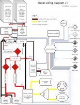
2020 solar.jpg
 
What I see there makes sense.
Check voltages of things before connecting, for instance make sure PV panel strings are the same voltage, correct voltage, correct polarity before closing breakers. Check voltage between battery terminal and cable before connecting, between battery strings before paralleling, voltage and polarity from battery side of switch to inverter and converter before closing switches.

It shows 800W of panels for about 4kWh/day production, also 4.8 kWh of battery. I like excess PV capacity but you're probably area limited.
You could deploy more panels as portable, if same voltage/series configuration as existing could be paralleled into same charge controller.

Yes, 24V devices would go to the 24V rail and negative busbar (which is after shunt, so load current is measured).

You drew your 4s2p PV joining at a "Y" which is OK if box they go to is fused suitably (about 20A), but since it is as combiner box it probably takes in 4s1p + 4s1p, might have 12A or 15A fuse/breaker guessing based on < 6A panel.

10 awg is plenty thick for the 15A or so from PV, but after MPPT SCC for 60A fuse should use 6 awg.
800W/24V = 33A so 10 awg is kind of OK (ampacity is 40A), but per NEC we would fuse at 30A. Maybe mobile application is OK at 40A. Better to use at least 8 awg (which is OK for 60A fuse if single conductors in free air) or 6 awg.

If 90 degree insulation, single 4/0 wires are rated 405A but not 600A. The 600A fuse will protect against shorts, but not moderate overloads. Any reason not to have a 400A fuse there? I don't see more than about 250A of loads. Wire and fuse should be sized so fuse never blows except in case of a short. Are downstream circuits protected at lower total current, for instance a breaker inside the inverter?

8 awg to converter, should be plenty for the 35A at 24V needed to provide 70A at 12V. But is there overcurrent protection?
Thanks Hedges. the heads up on power checks a long the way is a good idea and i might have not thought to so a good heads up. I will review and revise the fuses in my plans. i just dropped in the values that were on the victron map and have not run calculations since drawing up my diagram. as for your questions. i need to sit down after work in go over them and get some answers.

-Warped
 
Back
Top