diy solar

diy solar

Giandel inverter neutral-ground bond in off-grid system

Hi all, I am looking at a similar problem with Giandel. I have not yet purchased Due to topics on this thread. I found the following video which appears to tackle this problem. I will also be purely off grid 100% solar only. It appears that Giandel advises against doing this 'fix'. I am leaning towards a UL / ETL / CSA approved product with internal ground neutral bonding now unless you guys have some thoughts (more than above) on this below video:


Thanks!
 
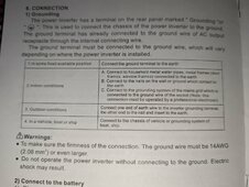
I also found this in the Giandel manual:

6. Connection

1) Grounding The power inverter has a terminal on the rear panel marked " Grounding "or " ". This is used to connect the chassis of the power inverter to the ground. The ground terminal has already connected to the ground wire of AC output receptacle through the internal connecting wire. The ground terminal must be connected to the ground wire, which will vary depending on where the power inverter is installed. In a vehicle, connect the ground terminal to the chassis of the vehicle. In a boat, connect it to the boat's grounding systems. In a fixed location, connect the ground terminal to earth.

So yes test the ground to neutral bonding to make sure on the inverter. Then if it is bonded as it stated, running the AC to a panel (eg Romex), connecting to the ground bus and connecting the grounding bus to earth (rod or plate) should be all you need - I do not see the need to even use the grounding screw on the chassis if there is a ground neutral bond as stated.

I did notice the inverter is ETL approved. As for GFCI, with a sub panel and earth ground I do not see how this would trip a GFCI as there is only one path to ground through the panel.

This totally changes how I am installing my system in my 'bunkie' / tiny off grid home - I see the need to install a small panel with either GFCI outlets or breakers (especially the one I am running outside for a soft start shallow well jet pump / tools.

I have a few electrical engineer friends that are up on solar, I'll be sure to ask them also. Thanks for the great discussion as always (I am still a big noob here).
 
Nothing in your quote from the manual states there is a ground /neutral bond. You're mistaking the bond from chassis screw to earth output. Neutral is not mentioned. You should still connect neutral to ground in a single location, preferably behind a gfci/rcd device.
 
Nothing in your quote from the manual states there is a ground /neutral bond. You're mistaking the bond from chassis screw to earth output. Neutral is not mentioned. You should still connect neutral to ground in a single location, preferably behind a gfci/rcd device.
you are correct - it does not appear to have a ground neutral bond (I just wanted people - myself included - to check. I am sorry for the poor wording. It says the chassis and ac ground are bonded. To me this means you either:

1. ground the inverter to earth from the grounding screw or
2. ground your sub/load panel to earth
 
Hi all, I am looking at a similar problem with Giandel. I have not yet purchased Due to topics on this thread. I found the following video which appears to tackle this problem. I will also be purely off grid 100% solar only. It appears that Giandel advises against doing this 'fix'. I am leaning towards a UL / ETL / CSA approved product with internal ground neutral bonding now unless you guys have some thoughts (more than above) on this below video:


Thanks!
I followed Roland's advice as per the video you linked and it worked perfectly.

My inverter is a Reliable Electric (WZRELB) 5kw high frequency, I also own the 3kw version of the same brand, which also worked fine using this method. Earth bond at the load centre (not at the inverter) was the ticket.
Tested the system multiple times with a Megger rcd tester and all good, with ground fault trip times in the 7msec range.

His advice is sound, at least in my case with this inverter type, I had no trouble creating a TN-S system.
He has a number of videos on this subject, they are all worth a watch.
 
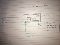
Ok, so I spoke with my electrical engineering friend about this grounding and yes, you would only ground at the panel. You would treat the panel as a main panel where the neutral bar has a lug that screws down to the panel and the ground lug goes to earth ground. So when the ground bar/lug is attached the the panel this creates your ground neutral bond as you would in a normal house service panel. I would use a GFCI with this arrangement.

Again, I would definitely check that there is no ground - neutral bond in the inverter as a precaution. As Giandel states in the manual only the ground and chassis are bonded. Use this with caution and do your own research as always. This will suit my off grid needs.
 

Attachments

  • IMG_7201.JPG
    IMG_7201.JPG
    486.4 KB · Views: 16
I have the same issue. What I have found is that most small inverters are internally bonded. This means that the panel should be wired as a subpanel to prevent having a double bonded scenario. I do not know how well this will work. Some say the panel could become a conductor because of the type of output of the invertor.

One thing that I have found is that some of the smaller inverters, < 3kw have the bond with a relay that is normally closed which can be checked by measuring the continuity between the neutral, ground and chassis lug. Other units as in the some of the Victron units have a relay or relays that are normally open and will close when the unit is turned on. These are hard to evaluate if they are internally bonded.

Also if the invertor has an AC input, when in use this will unbond the AC output. Maybe this is not an issue if the AC in source is from a bonded source, but what about if it is a generator that is not bonded. Then nothing would be bonded in the circuit.
Thanks. I have checked the inverter manual. There is no internal ground neutral bond and it does not 'float' or switch. The ground of the inverter (Giandel 24V 3000W) is only attached to the ground plugs of the AC output.
 
Thanks. I have checked the inverter manual. There is no internal ground neutral bond and it does not 'float' or switch. The ground of the inverter (Giandel 24V 3000W) is only attached to the ground plugs of the AC output.
Using the breaker panel as a main with a bonded neutral and ground would be correct.

I may have to sell my inverter and by one of those units. I chose the Jupiter 3kw because it had a provision to be wired instead using the typical 110 receptacle. There is no way I can see to un-bond the unit I have.
 
PXL_20240416_003757351.jpg
I'm in the same situation looking for clarity , I just received a new giandel 3k inverter. after reading the manual which is different then the one listed on the website it stated for indoor condition which is my situation for off grid and the original question it states to hook ground to mains grounding system . so to me this sounds like bonding N and G in a panel which has an earth rod is correct .
 
Back
Top