diy solar

diy solar

Giandel inverter question

K5BEAST

New Member
Joined
Jul 17, 2021
Messages
9
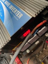
4000 watt giandel pure sine wave inverter suddenly shows an overload error/shutdown/buzzing with nothing connected to it. Tried restarting, even tried a different battery bank. Reads 12.6v input.

Any one know what would be causing this? Suspect something internal. Guess I'm gonna pull the cover and see what there is to see.....

Any help would be appreciated.
 
Yes, inverter has been the main power source for the last couple years
 
If it's still under warranty then it's best to try customer support first. Otherwise, some photos of the inverter internals would make it easier for people to help.
 
So last night i completely disassembled/ reassembled the inverter looking for anything burnt or out of place. Came up with nothing. Everything was clean, no dust, etc. Couldn't find any trace of anything burnt on the circuit boards. No burnt smell. Nothing at all. After reassembly, same results.
 
So last night i completely disassembled/ reassembled the inverter looking for anything burnt or out of place. Came up with nothing. Everything was clean, no dust, etc. Couldn't find any trace of anything burnt on the circuit boards. No burnt smell. Nothing at all. After reassembly, same results.
Did you take any pictures? No lytics capacitors with leaking electrolyte or bulging top? Bad lytics caps are one of the common failure.
 
Nope. No bad capacitors. None bulging. All flat tops, no leakage. Not my first electronic inspection. No loose connections (pins to board), no signs of any excess heat or short circuits. Shit, there wasn't even any dust.

Sorry, didn't take any pics. I emailed Giandel. Will see what they say.
 
If you haven't, you should check the output IGBT transistors to make sure none are shorted out.
 
Nope. No bad capacitors. None bulging. All flat tops, no leakage. Not my first electronic inspection. No loose connections (pins to board), no signs of any excess heat or short circuits. Shit, there wasn't even any dust.

Sorry, didn't take any pics. I emailed Giandel. Will see what they say.
Can you give us an update on this? I tried contacting Giandel team via ebay (where I purchased). Different issue where I need to know if it makes sense to connect a controller to it or if that would override the internal controller (PWM I believe). Likely I'll post the problem in a separate post on this forum. It's been a day and I have not heard back. Perhaps it's due to the holiday season. But I am wondering if its better to contact them via a different email.
 
I'm also interested in this thread as I'm looking at a Giandel 3000w 12V unit (PS-3000KAR) for $379 after a $30 coupon on Amazon. I just bought three 12V 200AH LiFePO4 batteries to parallel for 600AH. This is to power a 1988 28-foot class C RV with a 30A 120V electrical system.
 
Sorry, but I'm new here and this is my first post, I was searching about this very same problem as I have the same symptoms as yourself.

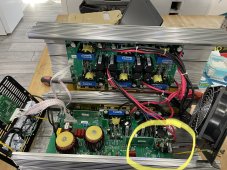
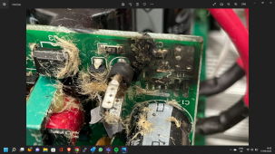
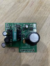
This is what I found... The heat sensor PCB board had blown a few components

6d2f24e2-5f18-4c03-9731-1cf5ba3c2d4a.jpgIMG_0215.jpgScreenshot (26).png
 
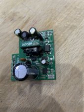
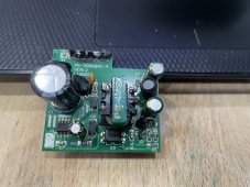
That is switching power supply PCBA (PCB PS-2000QAC-4 Ver.2), made by LINGQI inverter company.
Are the two big boards also have LINGQI printed on the boards too?
It looks like C3 was exposed to over Voltage so it blew up.
What is the DC Voltage rating of that big Lytics cap?
 
Last edited:
That is switching power supply PCBA (PCB PS-2000QAC-4 Ver.2), made by LINGQI inverter company.
Are the two big boards also have LINGQI printed on the boards too?
It looks like C3 was exposed to over Voltage so it blew up.
What is the DC Voltage rating of that big Lytics cap?
Only one of the two big boards has LINGQI on it the other doesn't.

Giandel said this was a heat sensor, something to do with the heat sensing.
Thought this funny as it didn't look as if anything on it was temp sensitive.

Over voltage could make sense, the inverter died as we left the services it maybe it spiked when I started the engine.
But Chassis battery is completely separate from habitation battery's :unsure: only thig connecting them is a trickle charger from hab to chassis.

The weird thing was the only debris found inside inverter was the yellow insulating stuff from C3 and its plastic case nothing of the IC chip was to be found.

Oh C1 voltage 450v 22uf
C3 Voltage 50v 22uf

I'm learning here, it's all good stuff
Thanks Bud
 
Last edited:
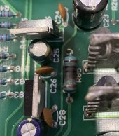
Wondering if I should change this 10 ohm resistor as it comes straight from the affected burnt out board and looks like it’s got hot at sometime must have been when the board blew out it’s giving 9.7ohm with a 5% tolerance so looks to be fine but should I change it as it discoloured as has ran hot I know the value and tolerance but how do I find the wattage?
On top of this the solider joints look a bit dry as well,
Physical size of resistor is 10mm x 4 mm wire size 0.3 mm which makes me think is 1Watt, so I'm thinking of replacing with a 2 Watt one.

Your thoughts here:
Replace with 2W
Replace with 1W
Leave as is just redo dry joints

BD5C30B3-5681-4658-8DB5-852C1CFD6AB2.jpeg
 
Last edited:
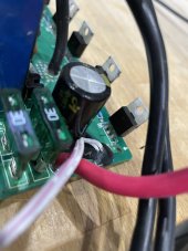
Have had a look at the mos-fets triacs thyristors what ever this is and this one is giving off different resistance to all others but there’s no ID on it to say what it is

Has anyone got any idea!!!
This is all new to me as my normal things are disco mixers amps and lighting controllers even this was 40yrs ago. So I’m a little out of touch here.96E03D99-E2D0-4684-B9D7-D745B2967915.jpeg
 
Last edited:
Only one of the two big boards has LINGQI on it the other doesn't.

Giandel said this was a heat sensor, something to do with the heat sensing.
Thought this funny as it didn't look as if anything on it was temp sensitive.

Over voltage could make sense, the inverter died as we left the services it maybe it spiked when I started the engine.
But Chassis battery is completely separate from habitation battery's :unsure: only thig connecting them is a trickle charger from hab to chassis.

The weird thing was the only debris found inside inverter was the yellow insulating stuff from C3 and its plastic case nothing of the IC chip was to be found.

Oh C1 voltage 450v 22uf
C3 Voltage 50v 22uf

I'm learning here, it's all good stuff
Thanks Bud
So this SMPS looks to be taking in high the AC input from some where (probably the 230VAC output of this inverter) and generates single the low Voltage DC to run something on the main board.
You cannot read the P/N printed on the SMPS IC U1?
D2, R2, and C3 are part of the startup/running cap to supply the VCC to run the SMPS IC U1.
D1. R1, and C2 are part of the snubber circuit on the primary winding of the SMPS power transformer.
U2 is probably xx431 shunt Voltage reference IC part of the Voltage regulation circuit, which drives OPTO U3.
U3 is the opto-isolator for feedback circuit to maintain regulated DC output.
The DC output is just a simple Diode rectifier with LC Pi filter.

R85 gets hot like that is not good, it is either under rated Wattage being use or just bad design, the resistor should have been mounted with spacing between the board and the body of the resistor to help cooling. I would replace it, it looks to be MOX Flame-proof resistor .

It the unit working right now?

It looks like GIANDEL have their inverter made by LINGQI.
 
Last edited:
Back
Top