diy solar

diy solar

Green Ranges Leisure EV Switch from lead acid Gel to Lifepo4 Cells

Green Ranges

New Member
Joined
Oct 27, 2021
Messages
6
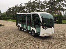
Hi, I am Ken which runs a one man company rental and sales business with Leisure EV's like low speed shuttle busses.

I have always been fascinated with Strong , Light weight Power packs, due to the heavy weights , slow charging and thereby limited energy of the Lead Acid / Gel battery packs we use currently. That brings me to the story hereunder : ( Not sure if Its oke to talk right away about my project at the introduction , ... dont blame me if its not :)

We offer our customers two standard factory supplied batteries :

1.serial connected 12 x 6V - 200 ah@3hrs ( 6.5 volts if fully charged ) Gel batteries pack which has a range of 60 km if new in summer time temps. and like 40 km on flat tracks in winter temps, like -10 celcius.
2. serial connected 12 x 6V - 260 ah@3hrs ( 6.5 volts if fully charged ) Gel batteries with range like 80 km and like 50-60 in winter temps.

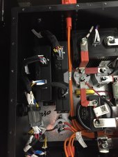
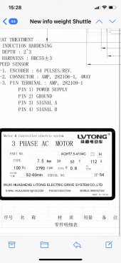
Controller into of our Shuttles : Toyota Controller ( 80 Volts - ( https://key-components.toyota-industries.com/products/controller/l_type/ ) Input DC power - Output AC power for Three fase E- Motor 7.5 kw AC.

Customers always ask what you cant deliver i think they have a nose for it ... heheh. If you able to give them 60 km range they ask for 80 if you tell them you able to give them 80 km range they ask to drive slopes ( which is a super drainer for EV ). Etc

That brings me to the point I got interested in the EVE Prismatic Cells serial connected and protected with an BMS.

Some things which give me questions :

* The EVE cells 280 / 304 ah are 3.2 volts . As you probably understand its important to have an voltage range which is suitable for my controller which is said to work at 80 Volts

- I need to know the know the fully charged EVE cell voltage ( seems to be 3.65 cut off charging voltage per cell ) and if 'rest' a while will drop to 3.5 volt and if have slight load on it they go to the solid 3.3 - 3.2 volts ( fully charged with load ) that brings me to the question : How many cells would be best for my solution and I dont exceed the max voltage of 80 volts of my controller. I was thinking about 23 cells x 3.35 Volts to be somewhere in the middle of top voltage 3.5 and lower 3.2 volt : 77.05 Volt. Means upper lever ( which is under the 80 Volts of the controller ) and the cutoff voltage of 2.5 volts x 23 cells : 57.50 Volt ( which is slight low for this system as 60 Volts as lower level would be more suitable to feed the controller.

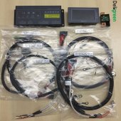
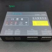
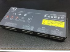
* Then the Bms , I see some fan cooled Daly BMS which are around 200 usd , which is a low price, so not really sure how safe they are and how reliable. I know they have an Bluetooth to read the values, a possible screen connecter, which is nice. But I also see and read a thread here on the forum about an PV input to the Daly BMS ( comparable setup as mine ) which feeded the BMS an overvoltage which make the Daly BMS Short circuit and ruined the EVE cells.

- What do you guys advice ? as a reliable BMS, as persons are carried in these Shuttles I want to think out a safe system ( I know my factory can suit an pack but if a cell is broken, not balanced or whatever I need to discuss much ) so I would like so see the possibilties to build an safe pack and then discuss with them, besides how much fun is it to build one yourself ..

- The Overvoltage to the BMS ( if choose Daly ) could only be caused by a failing charger for my setup and now like the PV overvoltage example on the thread I read before. The BMS I attached cost like 600 USD and seems way more advanced with solid Shunt and Screen etc then the Daly version.

Looking forward for some of your advices and reactions and I keep your updated after I will order - build and test all.

Thanks Guys

Kenny
 

Attachments

  • IMG_8691.JPG
    IMG_8691.JPG
    435.4 KB · Views: 2
  • LiFePo4 BMS Specification by Deligreen.pdf
    1.3 MB · Views: 2
  • Deligreen SMART BMS Catalogue.pdf
    9.3 MB · Views: 1
  • LF280N(3 2V 280Ah)Product Specification 2019 12 22(1).pdf
    727.3 KB · Views: 1
  • HTB1mst7hHZnBKNjSZFGq6zt3FXaw.jpg
    HTB1mst7hHZnBKNjSZFGq6zt3FXaw.jpg
    182.1 KB · Views: 2
  • HTB19JiohRjTBKNjSZFuq6z0HFXaB.jpg
    HTB19JiohRjTBKNjSZFuq6z0HFXaB.jpg
    785.6 KB · Views: 2
  • HTB1Gx99jsUrBKNjSZPxq6x00pXaf.jpg
    HTB1Gx99jsUrBKNjSZPxq6x00pXaf.jpg
    123.3 KB · Views: 2
OK, I see what you are thinking on BUT I have to say STOP !
Daly is a So-So BMS and they are FET Based which for a basic drop-in replacement battery or an offgrid (lighter use) implementation, they work BUT these are NOT INTENDED for EV Use ! Every EV Maker uses BMS' with Relays/Contactors simply due to the Amperage Loads being handled and THAT is a real Kick in the pants ! Volts are moot, Amps Rule.

LFP Nominal Voltage = 3.200V
LFP Full Voltage Range = 2.500-3.650V
LFP Working Voltage Range = 2.800-3.475 (Grade A+), 2.900-3.400 (Grade A), 3.000-3.375 (Grade B) and lower isn't worth mentioning.
80V LFP Pack would be a 25-S Configuration. Volt Range (A+ cells) would be 70V-86V

The Most A-Typical implementation uses a "Separate Port" type BMS. One port is used for Discharging (uses one relay/contactor) and one port is connected to the EV Charger system with its own Relay/Contactor. Each Relay would / should be rated to the Max Amp Draw potential +10% Margin minimum. (Depending on grade/quality of relays/contactors.) Tesla & GM use Panasonic Relays & Contactors, for example.

IS LFP correct for your application ?
Standard ESS/LEV grade LFP can ONLY Discharge at a Maximum of 1C-Rate. So a 280AH Cell / Battery Pack can only output 280A for 1 Hour MAX. There are NOT designed for such High Output to be delivered constantly, their "design target" is to not exceed 0.5C Discharge Rate max (140A). EV-LFP is different as it can typically discharge up to 5C some even higher but now you are talking Blade & CTP cells (virtually impossible to get). Alternately, Winstons Link: https://en.winston-battery.com/?cnxdc/ Which are Yttrium Doped and spec'd for LEV use. NB: These are Prismatic (Square Blocks). Alternately, Cylindrical LFP such as the 32700 family tend to be used for EV's due to the performance characteristics... Here is one site with a basic listing for your perusal. https://www.batteryspace.com/LiFePO4-Cylindrical-Single-Cells.aspx

It all really comes down to the Amperage demands of your driveline, so the batteries can handle not only the usual straight-line flat surface driving but when going up hill & the driver mashed the pedal Surges. If you are at a dead stop and then mash the pedal to the floor, what is the Amp Surge Demand ?

Your Motor Controller Info : Assuming worst case: 550A AC for 2 Minutes from 80 Volts is a big draw, BUT the AC Voltage is not mentioned so we cannot work out how many Watts it is. In turn that does not let us work out how many Amps are drawn from the battery bank to deliver 550A @ XXX volts. Amps X Volts = Watts.
ModelPower supply voltage [V]Output current [Arms] 2-minute ratingExternal dimensions [mm]
80L33080330
80L44080440
80L55080550

I hope it helps, Good Luck
Steve
 
Also I don't think the Lord Engineer Steve mentioned it (ah. He touched on it with the working range...I'm tired man) but you probably should avoid dropping them to 2.5v anyways. This solves the 60v thing and they'll last longer.

If you don't want to exceed 80v then the math is simple. 80/3.65 is 21.9 cells. So 21 cells is the limit if you ever have a possibility of charging them fully to 3.65.

If you have a quality bms and associated charger that you can program to cutoff slightly sooner you can avoid any cell hitting this limit and introduce additional cells to the tune of your 23 number. This would be a cell limit of 3.477v.

I should think that charging to a "custom" voltage like that is the bigger challenge.

If you avoid a full discharge to 2.5v and choose say 2.9 or even 3v instead (depending on your test results) you might find the loss in total capacity to be almost irrelevant because you're already approaching the last bit of capacity at that point. It'll also extend the life dramatically by avoiding a 100% DoD, and never hit the 60v minimum even with 21 cells, at least without a load.

Of course I'm sure you have higher discharge currents to worry about and will need to account for that voltage drop under load and all that which is where the 23 cells looks better.

Oh, and Steve is definitely the guy to talk to on this. So if he says I'm wrong about any of that, its definitely because I'm wrong.
 
Guys, ..

Let me first say Thank You ... for replies which give me value, as its very rare in these times people know what they talk about. About your STOP .. dont worry ... I am here at the forum to discuss and learn before i will Act.

Based on your reactions I would like to add following info :

The Controller is very reliable and the Factory used this Toyota controller which has itself also an adjustable cutoff voltage ( which i can set with software ) that would protect for example the batteries to in a secondairy line ( for example set them on 65 volts cutoff by controller. See for example picture 6 in attachement.

The shuttle has an DC battery input to the Toyota controller which converts it to feed the E Motor ( three phase 7.5 Kw AC ).

If I drive with the Shuttles now fully loaded ( 14 passengers ) the current draw I can also set by controller - for example I set the Power delay like 5 seconds - you push full throttle and the Toyota controller release the current drop in over these 5 seconds. That will flatten the amp draw curve too.

A thing about the controller nobody could tell me this ( even the main reseller of the controller which i asked - he send me to chinese resellers which also couldnt tell me ) - The controller says 80 volt .... What happens when it received more then 80 volts ??? Will it burn out ? is it protected ?? Its so frustrating nobody can tell ....

Some info about the amps drawn out of the pack :

Full throttle , amps pulled out of the battery pack will be like this :

Start Full throttle 0-5 seconds to max 225 ah - ( battery pack fuse is 250 ah ) - then if shuttle loaded with people has its startoff speed of 25 km/hrs the amps get stable on flat track about 50 amps continously - if slight slowing down / full throttle it would be around 150 ah max.

I thought these would be reasonable amp drawings for such EVE cells which like you say can do 0.5 ah normal discharge ( i got constand discharge like 150 amps MAX ) and a peak of 10 seconds like 225 amps.

if slowing down the Toyota controller is set the regenerative brake ( also and issue for my battery pack ??? as it might overcharge the batteries by this - even an BMS is connected to the cells , but the ''charging'' comes from the controller which wont be shut off as it charges the batteries depending on the force of the Shuttlebus.

We also sell COC approved vehicles which indeed have many relays etc - please note the attached picture 1 till 4 these had a 86 Volt pack ( with different lithium ( which is less safe in my opinion ) - Tesla has negotiations also with EVE Factory i read before even this Lifepo4 lithium is less energy densed but it more safe then previous lithium cells tesla used. ( no heat reactions etc i read )

The 6 th picture shows the Gel batteries which we currently use : 260 ah @3hrs .. they strong and good for 80 km range but : heavy !! and 500 cycles !! its done .. they accept 50 ah charging current.

The 7 th picture shows some packs used for my application and they also use EVE cells etc. So In my thinking it must be possible with some addings ...

About the Daly BMS I had a bad feeling it wasnt suitable so I indeed stop that ... ( for your info they showed me daly bms which could handle 250 amps charging and discharging even 500 amps .. so I dont know why they sell it then as it would be Ok for my amp draw )

Looking forward for next discussion - pictures and advices after reading my new updated info

Thanks a lot

Kenny ( Netherlands )

P.S : Steve S and Short Shot appreciated your comments ( reading / and thinking about your comments to discuss more )
 

Attachments

  • IMG_5945.JPG
    IMG_5945.JPG
    105 KB · Views: 3
  • IMG_8425.jpg
    IMG_8425.jpg
    396.9 KB · Views: 4
  • IMG_4114.PNG
    IMG_4114.PNG
    2.5 MB · Views: 5
  • IMG_3732.JPG
    IMG_3732.JPG
    195.2 KB · Views: 5
  • IMG_3731.JPG
    IMG_3731.JPG
    138.7 KB · Views: 5
  • IMG_3730.JPG
    IMG_3730.JPG
    141.9 KB · Views: 5
  • IMG_3722.JPG
    IMG_3722.JPG
    590.2 KB · Views: 4
Also I don't think the Lord Engineer Steve mentioned it (ah. He touched on it with the working range...I'm tired man) but you probably should avoid dropping them to 2.5v anyways. This solves the 60v thing and they'll last longer.

If you don't want to exceed 80v then the math is simple. 80/3.65 is 21.9 cells. So 21 cells is the limit if you ever have a possibility of charging them fully to 3.65.

If you have a quality bms and associated charger that you can program to cutoff slightly sooner you can avoid any cell hitting this limit and introduce additional cells to the tune of your 23 number. This would be a cell limit of 3.477v.

I should think that charging to a "custom" voltage like that is the bigger challenge.

If you avoid a full discharge to 2.5v and choose say 2.9 or even 3v instead (depending on your test results) you might find the loss in total capacity to be almost irrelevant because you're already approaching the last bit of capacity at that point. It'll also extend the life dramatically by avoiding a 100% DoD, and never hit the 60v minimum even with 21 cells, at least without a load.

Of course I'm sure you have higher discharge currents to worry about and will need to account for that voltage drop under load and all that which is where the 23 cells looks better.

Oh, and Steve is definitely the guy to talk to on this. So if he says I'm wrong about any of that, its definitely because I'm wrong.
Thanks !

I agree with you on the numbers of cells . About the voltage drop I dont have any experience yet with lifepo4 , thought they are very stable at their voltage even pull 200 amps out them they dont drop like my Gel battery voltage .

At my Gel batteries if fully charged 6.5 v x 12 : 78 volts : full throttle they drop at 200 amps to say 72 volts max and be stable around 75 volts when the vehicle has its speed.

with the controller i also can set a cutoff voltage of say 65 v that is for second line battery pack protection also nice i think.

Ken
 
OK, I see what you are thinking on BUT I have to say STOP !
Daly is a So-So BMS and they are FET Based which for a basic drop-in replacement battery or an offgrid (lighter use) implementation, they work BUT these are NOT INTENDED for EV Use ! Every EV Maker uses BMS' with Relays/Contactors simply due to the Amperage Loads being handled and THAT is a real Kick in the pants ! Volts are moot, Amps Rule.

LFP Nominal Voltage = 3.200V
LFP Full Voltage Range = 2.500-3.650V
LFP Working Voltage Range = 2.800-3.475 (Grade A+), 2.900-3.400 (Grade A), 3.000-3.375 (Grade B) and lower isn't worth mentioning.
80V LFP Pack would be a 25-S Configuration. Volt Range (A+ cells) would be 70V-86V

The Most A-Typical implementation uses a "Separate Port" type BMS. One port is used for Discharging (uses one relay/contactor) and one port is connected to the EV Charger system with its own Relay/Contactor. Each Relay would / should be rated to the Max Amp Draw potential +10% Margin minimum. (Depending on grade/quality of relays/contactors.) Tesla & GM use Panasonic Relays & Contactors, for example.

IS LFP correct for your application ?
Standard ESS/LEV grade LFP can ONLY Discharge at a Maximum of 1C-Rate. So a 280AH Cell / Battery Pack can only output 280A for 1 Hour MAX. There are NOT designed for such High Output to be delivered constantly, their "design target" is to not exceed 0.5C Discharge Rate max (140A). EV-LFP is different as it can typically discharge up to 5C some even higher but now you are talking Blade & CTP cells (virtually impossible to get). Alternately, Winstons Link: https://en.winston-battery.com/?cnxdc/ Which are Yttrium Doped and spec'd for LEV use. NB: These are Prismatic (Square Blocks). Alternately, Cylindrical LFP such as the 32700 family tend to be used for EV's due to the performance characteristics... Here is one site with a basic listing for your perusal. https://www.batteryspace.com/LiFePO4-Cylindrical-Single-Cells.aspx

It all really comes down to the Amperage demands of your driveline, so the batteries can handle not only the usual straight-line flat surface driving but when going up hill & the driver mashed the pedal Surges. If you are at a dead stop and then mash the pedal to the floor, what is the Amp Surge Demand ?

Your Motor Controller Info : Assuming worst case: 550A AC for 2 Minutes from 80 Volts is a big draw, BUT the AC Voltage is not mentioned so we cannot work out how many Watts it is. In turn that does not let us work out how many Amps are drawn from the battery bank to deliver 550A @ XXX volts. Amps X Volts = Watts.
ModelPower supply voltage [V]Output current [Arms] 2-minute ratingExternal dimensions [mm]
80L33080330
80L44080440
80L55080550

I hope it helps, Good Luck
Steve
Hi Steve,

Appreciate your reply and like to discuss more based on the new amp drawing info i gave. Did you check the BMS I showed you on the pic as that BMS is more suitable they told me for Low speed vehicles and comes with a automatic shut too if too much amps drawed to shut it off.

Ken
 
OK, I see what you are thinking on BUT I have to say STOP !
Daly is a So-So BMS and they are FET Based which for a basic drop-in replacement battery or an offgrid (lighter use) implementation, they work BUT these are NOT INTENDED for EV Use ! Every EV Maker uses BMS' with Relays/Contactors simply due to the Amperage Loads being handled and THAT is a real Kick in the pants ! Volts are moot, Amps Rule.

LFP Nominal Voltage = 3.200V
LFP Full Voltage Range = 2.500-3.650V
LFP Working Voltage Range = 2.800-3.475 (Grade A+), 2.900-3.400 (Grade A), 3.000-3.375 (Grade B) and lower isn't worth mentioning.
80V LFP Pack would be a 25-S Configuration. Volt Range (A+ cells) would be 70V-86V

The Most A-Typical implementation uses a "Separate Port" type BMS. One port is used for Discharging (uses one relay/contactor) and one port is connected to the EV Charger system with its own Relay/Contactor. Each Relay would / should be rated to the Max Amp Draw potential +10% Margin minimum. (Depending on grade/quality of relays/contactors.) Tesla & GM use Panasonic Relays & Contactors, for example.

IS LFP correct for your application ?
Standard ESS/LEV grade LFP can ONLY Discharge at a Maximum of 1C-Rate. So a 280AH Cell / Battery Pack can only output 280A for 1 Hour MAX. There are NOT designed for such High Output to be delivered constantly, their "design target" is to not exceed 0.5C Discharge Rate max (140A). EV-LFP is different as it can typically discharge up to 5C some even higher but now you are talking Blade & CTP cells (virtually impossible to get). Alternately, Winstons Link: https://en.winston-battery.com/?cnxdc/ Which are Yttrium Doped and spec'd for LEV use. NB: These are Prismatic (Square Blocks). Alternately, Cylindrical LFP such as the 32700 family tend to be used for EV's due to the performance characteristics... Here is one site with a basic listing for your perusal. https://www.batteryspace.com/LiFePO4-Cylindrical-Single-Cells.aspx

It all really comes down to the Amperage demands of your driveline, so the batteries can handle not only the usual straight-line flat surface driving but when going up hill & the driver mashed the pedal Surges. If you are at a dead stop and then mash the pedal to the floor, what is the Amp Surge Demand ?

Your Motor Controller Info : Assuming worst case: 550A AC for 2 Minutes from 80 Volts is a big draw, BUT the AC Voltage is not mentioned so we cannot work out how many Watts it is. In turn that does not let us work out how many Amps are drawn from the battery bank to deliver 550A @ XXX volts. Amps X Volts = Watts.
ModelPower supply voltage [V]Output current [Arms] 2-minute ratingExternal dimensions [mm]
80L33080330
80L44080440
80L55080550

I hope it helps, Good Luck
Steve
Some info on the 7.5 kw Ac engine attached for your info . The toyota controller is 330 or 440 I am not sure .. but not 550 type. And these are the max AC amps it can handle I assume ?

Ken
 

Attachments

  • A8A07A0B-A6AB-4FB5-98E1-ECBE78A0D8C0.png
    A8A07A0B-A6AB-4FB5-98E1-ECBE78A0D8C0.png
    938.2 KB · Views: 2
Well, now we have Regen Braking and more involved which of course further changes the picture slightly. I am NOT an E-Motive guy, i've tinkered with it and have some basics, I am a Solar Powered Off-gridder and other things...

Simply put on Daly BMS, they are quite well known for what they do but like all things, none are all what you want or need to be. You are looking at a different level of interaction with the batteries & devices on board. Have a Gander at the BMS' below and note the functionality & capabilities of these...

And for EV Level Gear This company addresses many (if not all) needs. (Tend to deal with Manufacturers not retail consumers)

Regarding Pack Voltage Calculations: It is customary to use Nominal Voltage which for LFP is 3.200 @ Mid-point of Working Range of 3.000-3.400.
80.0V÷3.200 = 25 cells. 25-S is NOT a supported Config, I used it for the metrics, I should have been more clear.
24x3.200=76.8V, range=60V-87.6V

Can the Controller take a 7.6V Overvolt ? If they don't know, I sure as heck wouldn't experiment. A Voltage Regulator should be available to handle that I would think.

Of the Lithium family of Chemistries, Yes, LFP at this point in time is the safest of the lot. Standard LFP cannot be charged below 32F/0C. from 32F/0C-50F/10C Reduced charging at 0.2 C-Rate is generally the recomendation. Yttrium Doped LFP can take charge to -20C/-4F and some specialty ones can go lower but at a very high $$$$ (BTW: CATL CTP & BYD Blade cells are Specialty & Doped, Very $$$ and impossible to get. The EVE cells we are talking about here are just normal LFP so If a human likes the temp, so does the LFP.

Rather than the 280AH cells, you may want to consider their 304AH cells as that gives you 150A Charge potential & 300A Draw potential. NB per Spec Sheets, these cells can also output a Burst of 5C for 10 seconds.

A Lurking Gotcha with LFP, unlike other variants it does do a deeper Voltage Sag depending on the draw. The sag also is depending on the current SOC and there's the gotcha, because the lower the cell voltage the deeper that sag will be and most especially pronounced when at the bottom of the working curve. LFP cells will ALWAYS deviate at both ends of the curve. Fully Matched & Batched Grade A Cells that have been properly & fully tested will maintain identical IR (Internal Resistance) throughout the Voltage Curve, whether charging or discharging and therefore deviate Minimally. NOTE: Properly Matches cells always test out above their designated / labelled capacity. Unmatched / Bulk cells have varying IR, they are only tested at the static testing voltage, these will virtually always deviate and may not ever even reach potential capacity.

For any form of EV use, the use of Matched/Batched & Binned cells is essential due to the nature of use and the loading on the cells. You absolutely do not want a Pack Failure (BMS Cutoff) because one cell deviates too much and causes a BMS Cutoff. Also the Higher the amperage PUSHED to charge LFP the more the cells within a pack with deviate (it's natural) so again having close / identical IR will prevent premature cutoffs & issues.

Known Good Reliable Vendor selling Genuine Matched Cells with Factory Report:

Lastly and pretty important too, No-One uses LFP from 2.500 to 3.650. From 2.850 to 2.500 and from 3.475-3.650 only represent's roughly 5-7% of the overall gross capacity which is usually left as reserve. IF you charge an LFP pack to 3.650V per cell and stop charging, within 1 hour the cells will have settled to around 3.500 +/- a bit pending on temps etc. This is again Normal Behaviour. Other Lithium chemistries settle as well but NOT as much as LFP.

In closing, I just dumped a lot of info... Sorry it's not all together but my day started at 03:00 and it's been one frantic day and I'm writing this on an extended break from doing things... had to take a recovery period, the body is in charge, not me. Download the LFP Voltage chart from the resources in my signature... There may be other handy things in my signature for you as well.

Good Luck, Hope it helps.
Steve

EDIT: Forgot a couple of References and Links you may find helpful as well.
Orion BMS is E-Motive and Top Notch gear:

and a Treasure Trove of tech info, some dated but all good.
 
Last edited:
Well, now we have Regen Braking and more involved which of course further changes the picture slightly. I am NOT an E-Motive guy, i've tinkered with it and have some basics, I am a Solar Powered Off-gridder and other things...

Simply put on Daly BMS, they are quite well known for what they do but like all things, none are all what you want or need to be. You are looking at a different level of interaction with the batteries & devices on board. Have a Gander at the BMS' below and note the functionality & capabilities of these...

And for EV Level Gear This company addresses many (if not all) needs. (Tend to deal with Manufacturers not retail consumers)

Regarding Pack Voltage Calculations: It is customary to use Nominal Voltage which for LFP is 3.200 @ Mid-point of Working Range of 3.000-3.400.
80.0V÷3.200 = 25 cells. 25-S is NOT a supported Config, I used it for the metrics, I should have been more clear.
24x3.200=76.8V, range=60V-87.6V

Can the Controller take a 7.6V Overvolt ? If they don't know, I sure as heck wouldn't experiment. A Voltage Regulator should be available to handle that I would think.

Of the Lithium family of Chemistries, Yes, LFP at this point in time is the safest of the lot. Standard LFP cannot be charged below 32F/0C. from 32F/0C-50F/10C Reduced charging at 0.2 C-Rate is generally the recomendation. Yttrium Doped LFP can take charge to -20C/-4F and some specialty ones can go lower but at a very high $$$$ (BTW: CATL CTP & BYD Blade cells are Specialty & Doped, Very $$$ and impossible to get. The EVE cells we are talking about here are just normal LFP so If a human likes the temp, so does the LFP.

Rather than the 280AH cells, you may want to consider their 304AH cells as that gives you 150A Charge potential & 300A Draw potential. NB per Spec Sheets, these cells can also output a Burst of 5C for 10 seconds.

A Lurking Gotcha with LFP, unlike other variants it does do a deeper Voltage Sag depending on the draw. The sag also is depending on the current SOC and there's the gotcha, because the lower the cell voltage the deeper that sag will be and most especially pronounced when at the bottom of the working curve. LFP cells will ALWAYS deviate at both ends of the curve. Fully Matched & Batched Grade A Cells that have been properly & fully tested will maintain identical IR (Internal Resistance) throughout the Voltage Curve, whether charging or discharging and therefore deviate Minimally. NOTE: Properly Matches cells always test out above their designated / labelled capacity. Unmatched / Bulk cells have varying IR, they are only tested at the static testing voltage, these will virtually always deviate and may not ever even reach potential capacity.

For any form of EV use, the use of Matched/Batched & Binned cells is essential due to the nature of use and the loading on the cells. You absolutely do not want a Pack Failure (BMS Cutoff) because one cell deviates too much and causes a BMS Cutoff. Also the Higher the amperage PUSHED to charge LFP the more the cells within a pack with deviate (it's natural) so again having close / identical IR will prevent premature cutoffs & issues.

Known Good Reliable Vendor selling Genuine Matched Cells with Factory Report:

Lastly and pretty important too, No-One uses LFP from 2.500 to 3.650. From 2.850 to 2.500 and from 3.475-3.650 only represent's roughly 5-7% of the overall gross capacity which is usually left as reserve. IF you charge an LFP pack to 3.650V per cell and stop charging, within 1 hour the cells will have settled to around 3.500 +/- a bit pending on temps etc. This is again Normal Behaviour. Other Lithium chemistries settle as well but NOT as much as LFP.

In closing, I just dumped a lot of info... Sorry it's not all together but my day started at 03:00 and it's been one frantic day and I'm writing this on an extended break from doing things... had to take a recovery period, the body is in charge, not me. Download the LFP Voltage chart from the resources in my signature... There may be other handy things in my signature for you as well.

Good Luck, Hope it helps.
Steve

EDIT: Forgot a couple of References and Links you may find helpful as well.
Orion BMS is E-Motive and Top Notch gear:

and a Treasure Trove of tech info, some dated but all good.
Steve,

Awesome that you react and I am ‘feeling’ you. You are same like me passionate in this field which I appreciate a lot. I will do some research now on possible BMS systems with relays which sound the most safe.

The regenerative function of braking I can possibly shut of .. so it won’t affect the batteries.

The supplier on alibaba I also know and had contact with good to know they have experience .

I bought an hioki meter some months ago which I played with my Gel batteries to see their inner resistance ( even it was expensive I just wanted to have it to know what I was doing ).

Any idea for an suitable voltage regulator ? And offcource I need to keep the amps in mind for that right ?

Take your time for reply ..

Ken
 

Attachments

  • 872B6AE9-CD8A-4DBA-8A4F-DE44AC871631.jpeg
    872B6AE9-CD8A-4DBA-8A4F-DE44AC871631.jpeg
    166.3 KB · Views: 1
  • 04E9FA3C-15FC-42D1-887E-D848C00C04F5.jpeg
    04E9FA3C-15FC-42D1-887E-D848C00C04F5.jpeg
    363.7 KB · Views: 1
Back
Top