I'm in the process of installing a 36 bifacial panels rated at 360 W each with 2 Growatt MIN 6000 tl-x inverters. Attached is an electrical diagram which details the components. I think its right but would like someone with experience to review it. I've been in the industrial electrical industry my entire career but have never had to deal with NEC on the residential side. Thank you in advance for your interest in my project.


You are using an out of date browser. It may not display this or other websites correctly.
You should upgrade or use an alternative browser.
You should upgrade or use an alternative browser.
Grid tied electrical diagram review
- Thread starter Repman
- Start date
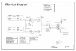
Mopat, thank you for your interest. I'm not sure if I need a DC disconnect between the panels and the inverter, The Inverter has a rotatory "DC switch" but their manual shows a separate DC disconnect as a component in their line diagram, (see page 3 of attached manual.) Yes, this will be installed in Flower mound Texas. I submitted the same electrical drawing to my Utility, Coserv and they gave me preliminary approval. Why do you ask about Growatt? They are UL (ETL) approved, see attached certificate.
Attachments
MarkSolar
Solar Enthusiast
It says the subpanel is existing, but doesn't show any utility power coming into it. Can't tell if it's oversubscribed or not with the added PV power. Main shows 200A breaker, backfeeding through 60A breaker. That would exceed 120% rule unless panel bus is rated for 225A.
Last edited:
MarkSolar, Thank you for your interest.
The subpanel has a 2 pole 20A breaker for my pool pump, and one 15A breaker for my pool lights. I'd like to add one 1 pole 15A breaker for patio lights and two 2 pole 30A breakers for the inverters.
Would backfeeding through a 50Amp breaker be within the 120% rule of a 200A buss?
The subpanel has a 2 pole 20A breaker for my pool pump, and one 15A breaker for my pool lights. I'd like to add one 1 pole 15A breaker for patio lights and two 2 pole 30A breakers for the inverters.
Would backfeeding through a 50Amp breaker be within the 120% rule of a 200A buss?
Hedges
I See Electromagnetic Fields!
- Joined
- Mar 28, 2020
- Messages
- 20,535
If the inverters are 6000W and 240V, that's 25A nominal.
"Max OCPD rating 26A" is inconsistent with that, should be 1.25x or 31A minimum (you show 30A in panel), 2
200A bus x 120% rule = 240A total; 240A - 200A = 40A max backfed breaker.
1) Double-check main panel busbar rating. If 225A not 200A, then you're fine.
2) Consider replacing 200A main breaker with smaller one.
3) Consider replacing panel with one having 225A busbar
4) Program inverters to produce less power (clipping maximum)
5) Multiple orientations of PV panels (rather than all 14 degrees on patio roof) would reduce peak
6) Is meter in separate enclosure from main panel? add a 200A fused disconnect, branch after that to 200A main panel and some appropriate main breaker in sub-panel
Existing sub-panel would also have 120% rule. If it has 125A busbar, then OK with 60A OCP and 2x 30A PV backfeed breakers (locate at far end of busbar.)
Hedges , Thank you for your interest .
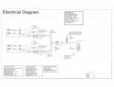
Originally, I had planned to use two 5Kw inverters and connect to the utility with a line side tap. Then, the 6kW inverter became available for a few dollars more and I noticed I had a subpanel exactly where the inverters were going to be located and thought I could save some money by using the existing wiring. (I think I forgot to update the OCPD rating when I switched from 5kW to 6kW.) It looks like that will not offset the cost of replacing the main breaker or the entire panel. Even if I did use the 5kW inverters, the nominal amperage would be 20.83 nominal, 26.04 max OCPD. , multiply x 2 = 52.08 which still exceeds the 40A max. so I don't see how the subpanel scheme will work without spending a bunch of money.
Attached is my original plan using the 5kW inverters, and the line side tap. I would like to use the 6kW inverters since I wouldn't be limited to the 120% rule. Your comments would be appreciated. Also attached is a photo of the structure that the panels will be installed on.
Attachments

MarkSolar
Solar Enthusiast
If you can install a line side tap your problems are solved and you can use the 6kw inverters. You might check with your utility company, some have meters that have a line side tap built in, that makes it easy to connect without touching existing wiring.
MarkSolar
Solar Enthusiast
You will need an AC disconnect, I'd put that right next to the meter and use it to connect the lines from your inverters. I don't have a specific recommendation but an AC 60A disconnect is probably $100ish.Mark, that's a good thought, I'll check with Coserv, my utility. Do you have a recommendation for the component(s) between the inverters and the line side tap?
Yes that's what I figured in the drawing but fused or non-fused?
I don't know what is NEC compliant, to run a set of wires to each inverter from the disconnect or a single set to a junction box near the inverters and then break it out to each inverter there?
Also, Would 30A circuit breakers be required after the inverters and before the disconnect?
I don't know what is NEC compliant, to run a set of wires to each inverter from the disconnect or a single set to a junction box near the inverters and then break it out to each inverter there?
Also, Would 30A circuit breakers be required after the inverters and before the disconnect?
MarkSolar
Solar Enthusiast
Sorry, I don't know the code for line taps. Where you combine the wires depends on distance and relative cost of the wire. Probably cheaper to combine at the inverters and run one wire up to line tap. There's a couple guys on the forum who have put in line taps, hopefully they'll chime in. You could also jump on an electrical forum and ask there. I use the electrical forum of diychatroom.com for that kind of stuff.Yes that's what I figured in the drawing but fused or non-fused?
I don't know what is NEC compliant, to run a set of wires to each inverter from the disconnect or a single set to a junction box near the inverters and then break it out to each inverter there?
Also, Would 30A circuit breakers be required after the inverters and before the disconnect?
Hedges
I See Electromagnetic Fields!
- Joined
- Mar 28, 2020
- Messages
- 20,535
Yes that's what I figured in the drawing but fused or non-fused?
I don't know what is NEC compliant, to run a set of wires to each inverter from the disconnect or a single set to a junction box near the inverters and then break it out to each inverter there?
Also, Would 30A circuit breakers be required after the inverters and before the disconnect?
Obviously line-side tape needs to be fused, I was going to comment on that when I saw the schematic.
You can get fused disconnects of various sizes. I have 30A, 60A, 100A.
This fuse needs to be rated to interrupt utility fault current, typically 22kA or greater (that's what main breakers are rated for.) Many fuses are rated 100kA or 200kA interrupting.
But for a line-side tap, is there an amperage limit? PG&E can put an adapter under the meter, but limited to 40A. Maybe that is just the adapter? But I would think line side tap 60A fuse plus 200A main breaker would be 260A that could potentially be drawn from their wires, not sized for that.
That's why I suggested a 200A fused disconnect between breaker and main panel. Then you can do your own "line side tap" on the line side of main panel, anything up to 200A.
After the line-side tap and fused disconnect, then fuses or breakers for each inverter.
I have a 100A fused disconnect (after a 200A main breaker in meter panel), and I stuffed two, 2-pole 63A DIN breakers in it. Also wired to surge arrestor.

In the drawing, 1/2" EMT? if it is straight, and you can stuff the wires. I like to use oversize conduit.
Hedges, thank you for your detailed answer. Could you check my sizing of the components, and wire?
Wire size from Inverter to Circuit Breaker : 10AWG THHN
Circuit Breaker rating: 30A
Wire size from CB to Fused disconnect: 10AWG THHN
Fused Disconnect rating: 60A
Wire from Disconnect to Line Tap: 6AWG THHN
Thanks!
Wire size from Inverter to Circuit Breaker : 10AWG THHN
Circuit Breaker rating: 30A
Wire size from CB to Fused disconnect: 10AWG THHN
Fused Disconnect rating: 60A
Wire from Disconnect to Line Tap: 6AWG THHN
Thanks!
Hedges
I See Electromagnetic Fields!
- Joined
- Mar 28, 2020
- Messages
- 20,535
6 awg is good for 60A fuse (I use it for 70A)
10 awg is good for 30A.
If more than 3 current-carrying conductors in cable or conduit, then there is derating to lower current allowed.
Also if in hotter than normal environment.
Hot "Line" wires count as current-carrying. Ground does not, and neutral in split-phase 120/240V does not.
Because 10 awg has 40A ampacity (although no larger than 30A fuse allowed), even though you have 4 hot wires going to two inverters, the derating still allows 30A fuse.
Your drawing shows two separate 30A disconnects (fused?) after the breaker panel with 30A breakers.
Utility may want a visible-blade disconnect, to be absolutely certain power source is isolated.
But do they require a single switch, rather than two separate ones? I don't know.
Mine has a single switch, branching to multiple breakers downstream.
You could put a single switch before the sub-panel. Which of course means any loads there would be shut off at the same time.
Or a single 2-pole breaker in the panel, feeding a 60A switch, and multiple branches of fuses/breakers downstream (like I did.)
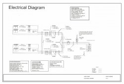
The drawing you're referencing incorporated a subpanel which I had to abandon because my buss won't accommodate more than a 40A backfeed.
Attached is a new drawing which incorporates a line side tap, a 60A fused disconnect and two 30A 2 pole breakers
Attached is a new drawing which incorporates a line side tap, a 60A fused disconnect and two 30A 2 pole breakers
Attachments
Last edited:
MarkSolar
Solar Enthusiast
I can't remember if you already bought the inverters. If not you could use one 12kw inverter and avoid the hardware to join the two 30a legs. Also might be cheaper.
MarkSolar
Solar Enthusiast
Similar threads
- Replies
- 0
- Views
- 248
- Replies
- 3
- Views
- 560