diy solar

diy solar

Grounding and bounding recommendations

Froostix

New Member
Joined
Aug 23, 2022
Messages
5
Hi there,

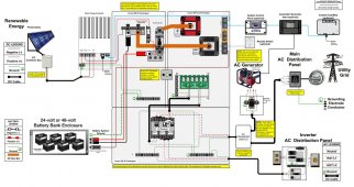
I am in the process of installing an off-grid solar system using Schneider electric products. I am basically following the schematic provided by Schneider (see attached) with no tie to the grid as I am completely off-grid.

My system in a nutshell: 3000W solar array + 20KW battery bank (48V) + 4000W inverter/charger.

I have installed the solar panels and I am getting ready to install the rest of the equipment. The previous owner had a generator tied to the house and I am planning to reuse it to recharge my battery bank when sunlight is scarce. The generator is a Honda EM5000SX and is located roughly 100m away from the house. The generator is tied to a grounding rod.

My questions:
1/ After reading forums and documentation of my charge controller (Schneider MMPT 60 150), it looks like it does provide a "negative ground bond for negative grounded PV array systems". Does this mean that I should only make sure there is no bonding at the generator?
2/ Is it safe to use that grounding rod for my system as is or is it too far from the rest of the equipment (100m)?

I will post a schematic of my installation tomorrow to better illustrate my plans.
Thank you for your help
 

Attachments

  • Schneider-Wiring.JPG
    Schneider-Wiring.JPG
    152.9 KB · Views: 35
Sorry for the delay, life got busy all of a sudden! :)

I attached the diagram of my system to this message.

I figured that I will put the grounding rod closer to my home, directly at the PV array combiner box (nowing that the generator will not always be plugged in to the system, I cannot rely on the generator ground)

The question that remains is that I need a negative bond to ground somewhere in my system. I read that most people do it at their main AC panel (directly after their counter if tied to the grid). My problem is that I do not have an AC panel... So where would you recommend that I put that ground bonding in my system? Also the notice of the Schneider Charge Controller (MPPT 60 150) does mention that it has a negative bond to ground by default. Would that be enough? I feel like I am missing something...

Thank you for your help!
 

Attachments

  • SolarDiagramV3.pdf
    71.5 KB · Views: 31
OK... From what you say, there will be no grid input to the system and the only distribution box is the Conext SW AC in your diagram.

The key to understanding what needs to be done is in the inverter installation manual (Page 1-23)

1661482909440.png
The inverter is what I call a 'common neutral' inverter: The inverter never switches or disconnects the neutral between input and output. Therefore it is expecting a single Neutral-Ground bond in the total system. (The inverter does not provide an N-G bond in any situation)

For a system that is connected to the grid, the single N-G bond is in the breaker box at the service entrance (Before feeding to the inverter).
Your system does not have that so the next logical place for the N-G bond would be in the Conext SW AC box. You can accomplish this with a jumper between the ground and neutral bus bars in the box. The Conext SW AC box is also the most logical place to put the connection to earth ground.

What generator will you have? It should *not* have an N-G bond. Most small gas generators do not have an N-G bond, but when you get into larger 220V generators, they might have an N-G bond. As far as I know, all of the larger generators that have an N-G bond also have a way of removing the bond.

Overall, your system looks pretty good. I am a little concerned that the effective AH of the battery bank is on the low side for a system that size. Have you done an energy audit to calculate the system needs? If not, that should be the next thing you do (before anything else) This is the tool I use:

 
Wow! Thank you so much for the fast and detailed answer!

I was a little worried to modify the cabling in a pre-wired unit like the AC switchgear but it does make perfect sense to have the N-G bond in this location in the absence of a main AC panel. Of course, I will be checking my generator for a existing NG bond and remove it. It is an older Honda EM5000SX and the notice does not mention any bond, but I'll test it myself with a voltmeter this weekend.

I understand the AC box is also the most logical place to put my connection to earth ground. Unfortunately, this is not the most convenient... Would there be any downsides (safety issues, performance...) connecting the earth ground at the PV array combiner box?

As for sizing of the system, I did create my own basic spreadsheet (see attached), quite similar to yours but not as advanced! That'll give me some food for thoughts! Anyway, I did run my parameters in your calculator and it looks I am pretty good. What do you think?

PS: panels are already up on the roof!!! ;-)
 

Attachments

  • House-SolarSystem.pdf
    134.8 KB · Views: 11
  • 296052631_579779010554241_3180173894674692174_n.jpg
    296052631_579779010554241_3180173894674692174_n.jpg
    524.7 KB · Views: 16
It is an older Honda EM5000SX and the notice does not mention any bond, but I'll test it myself with a voltmeter this weekend.
Most hondas do NOT have an N-G bond..... but it does not hurt to check.

Would there be any downsides (safety issues, performance...) connecting the earth ground at the PV array combiner box?
It would be a bit unorthodox. The NEC requires it at the service entrance, but you don't have a service entrance..... I am not exactly sure what the rule is in this case, but it is most likely that it needs to be at the power source (the inverter). Having said that, it is probably fine to rout it to the combiner box and then to the breaker box as long as it is large enough all the way to the breaker box. The primary issue is that someone not familiar with the set-up might disconnect ground at the combiner box and not realize they have disconnected ground from the whole system.
As for sizing of the system, I did create my own basic spreadsheet (see attached), quite similar to yours but not as advanced! That'll give me some food for thoughts! Anyway, I did run my parameters in your calculator and it looks I am pretty good. What do you think?

A few thoughts:

Your total watts with everything on is 1109. Even with some expected growth, a 4000 Watt inverter seems large.

Your buffer adjusted energy usage is 7855W. Your available watt hour storage with the lead acid is ~ 1/2 x 460 x 52 = 11,960Wh. That is less than 1.5 days of storage..... A couple of rainy days in a row and you could be filling the tank on your generator.

I don't know where your cabin is, but I will assume an insolation number of 5 for your area. That means your absolute max production on a sunny day will be 8 x 480 x 5 = 15350Whr. However, you can never expect to get the full-rated wattage out of the panels. 80% is typical so with full sun .8 x 15360Whr x .8 = 12288Whr. I notice there is shade in the picture so it could be less. This means if your battery is all the way down, it would require 2 full days of sun to charge the batteries while you are also consuming power in the cabin.

Overall, the system looks workable but
1) The energy storage (Watt hr) and energy production (Watt hr) may be a little on the low side for your needs.
2) The power capability (Watts) of the inverter is a little on the high side for your needs.
 
Thank you FilterGuy.

My generator had a N-G bound that I removed. I moved my grounding rod closer to my house and I am using the provided NG bond installed by default on the charge controller MPPT 60 150. So far so good.

I'll open a new thread for charge settings recommendations.

Cheers!
 
Wow! Thank you so much for the fast and detailed answer!

I was a little worried to modify the cabling in a pre-wired unit like the AC switchgear but it does make perfect sense to have the N-G bond in this location in the absence of a main AC panel. Of course, I will be checking my generator for a existing NG bond and remove it. It is an older Honda EM5000SX and the notice does not mention any bond, but I'll test it myself with a voltmeter this weekend.

I understand the AC box is also the most logical place to put my connection to earth ground. Unfortunately, this is not the most convenient... Would there be any downsides (safety issues, performance...) connecting the earth ground at the PV array combiner box?

As for sizing of the system, I did create my own basic spreadsheet (see attached), quite similar to yours but not as advanced! That'll give me some food for thoughts! Anyway, I did run my parameters in your calculator and it looks I am pretty good. What do you think?

PS: panels are already up on the roof!!! ;-)
Well that's just an adorable little cabin! Did you build that?
 
The NEC requires it at the service entrance, but you don't have a service entrance..... I am not exactly sure what the rule is in this case, but it is most likely that it needs to be at the power source (the inverter).
I am using the provided NG bond installed by default on the charge controller MPPT 60 150. So far so good.
I’m assuming a typo here and you meant to say AIO inverter, often just referred to as ‘inverter?’
Charge controllers do not have a N or G to bond.
 
Back
Top