diy solar

diy solar

Grounding batteries?

Jims94vmx

New Member
Joined
May 23, 2020
Messages
152
I have 2 BB batteries. moving from up front storage area in 5th wheel (stock battery location), moving under steps next to the PD converter.

In stock location the battery negative was grounded to frame.

The plan is to keep the existing wire run to the front (with a few tweaks) and using the 2nd positive and negative on the PD direct to the new batteries. Only ground now is the bare copper attached to the converter.

So is it okay to just run a positive and negative to converter (with a shut off on positive) and call it a day?

Then comes the inverter. It has a grounding wire that I need to attach somewhere. can I ground that using the bare copper wire going from the converter and fuse panel to frame.....

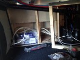
Pic of where I will be putting batteries. one just laying to get idea and measurements to fit.20200911_173109.jpg
 
Not enough information to know what you are doing.
 
Working towards solar. I have pretty much everything but the panels. Just moving BB from standard front compartment of 5th wheel to inside storage bay beside converter.

20200914_163205.jpg20200914_163205.jpg
 
I am interested in this also.

I have mounted my inverter and I need to ground the inverter to the frame. I plan on tapping into the nearest bolt to the frame for a ground that is already there, if I can find one.

My plan was to trace some of the copper wires to where they are frame mounted. Part of this is I have a steel frame the wheelbase sits on, and sitting on top of that I have a 2 1/2” X 1 1/2” Aluminum frame, at least for the storage compartment below the bedroom. To my beginner thinking that is two different frames, and my guess is the electricity would be grounded to the closest frame, the aluminum one. If this were the case, I don’t know how well the aluminum frame is connected to the black painted ground frame, whether its’s bolted, or welded, and how well a ground will work.

Anyway, that is one of the things I will be tracing down over the next few days.
 
I would not use the aluminum frame as the grounding point. The steel frame is the way to go.

My trailer has aluminum structure for the walls, but a steel frame. I used the existing point on the frame where the OEM battery negative lead was run to for my ground.

My new system does not rely on the ground for the negative lead. I run an explicit set of negative wires (same gauge as the positive wires) from the battery (bus bar in this case) to the load point that needs a negative connection. The frame ground is used by those components that explicitly state they must be grounded, such as the inverter, converter and solar charge controllers.
 
It is still very confusing for what you want to do. Addressing RV or van system, here are my ideas. Inverter has a positive dc and a negative dc. There is a case lug that is called ground in some books. As inverter pulls higher amperes I always run both positive and negative cables to the battery, or the corresponding buss bar. I connect the negative buss bar to chassis. I connect the case lug to the chassis. I use the chassis as the common negative 12 vdc reference. The chassis is also used by the inverter as its common 120 vac ground reference. Relocating the battery bank, could use longer cables from o/e location to new location. I would definite use negative return cables and be careful using exclusive chassis negative returns.
 
My PD converter has 2 positive and 2 negative inputs. the original wiring went to the circuit breaker panel then up front to a shut off switch and 4 position bus bar/circuit breaker. My original battery positive went to the bus bar and negative went to chassis ground.

Moving batteries now under the steps to converter using the 2nd set of outputs for positive and negative on converter. I have no grounding point other then the converter bare copper wire going into 5he circuit breaker panel then chassis
 
That is the 1st question....can I just run the cables positive and negative and not worry about another ground from batteries to chasis
 
It is still very confusing for what you want to do. Addressing RV or van system, here are my ideas. Inverter has a positive dc and a negative dc. There is a case lug that is called ground in some books. As inverter pulls higher amperes I always run both positive and negative cables to the battery, or the corresponding buss bar. I connect the negative buss bar to chassis. I connect the case lug to the chassis. I use the chassis as the common negative 12 vdc reference. The chassis is also used by the inverter as its common 120 vac ground reference. Relocating the battery bank, could use longer cables from o/e location to new location. I would definite use negative return cables and be careful using exclusive chassis negative returns.

edit: can you clarify the part in red.

I agree with this answer, with two caveats (1) in general, follow the advice given in your equipment manuals if there is any (2) I would do the same as ZIL with the exception of connecting inverter ground lug, and other equipment ground connections to the negative Busbar not the vehicle-chassis.

Both positive and negative should be wired properly.

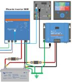
Here is an example from Victron, which reflects my understanding of DC side grounding for vehicles/boats:
Screenshot_20200602_175918.png
 
Last edited:
My grounding is close to that shown in the Victron diagram. All components that call for a ground, get a ground through a dedicated ground bus bar. Eventually, the battery does go to ground, but not through the dedicated ground bus bar.
 
It is still very confusing for what you want to do. Addressing RV or van system, here are my ideas. Inverter has a positive dc and a negative dc. There is a case lug that is called ground in some books. As inverter pulls higher amperes I always run both positive and negative cables to the battery, or the corresponding buss bar. I connect the negative buss bar to chassis. I connect the case lug to the chassis. I use the chassis as the common negative 12 vdc reference. The chassis is also used by the inverter as its common 120 vac ground reference. Relocating the battery bank, could use longer cables from o/e location to new location. I would definite use negative return cables and be careful using exclusive chassis negative returns.
If you are returning current to the battery negative through sheet metal you are doing it wrong. Every device with the possible exception of some 12V bulbs has both a positive and a negative power terminal. Wire both to your battery and it will work.

Automotive wiring quit using the chassis for a return current path a long time ago. Doing this can lead to corrosion.

Grounding the battery negative is not likely to cause a problem and without it you might build up a static charge on your dc wiring. The best way to ground is by means of a dedicated ground wire run from the main vehicle ground (where the alternator and starter battery grounds are connected). This is much better than connecting to some random piece of sheet metal in your vehicle that might not actually be grounded due to paint or damage repair.
 
Last edited:
  • Like
Reactions: Dzl
At least on an RV trailer, I think the manufacturers use the chassis ground to save wiring costs and the labor to run the extra wire. I certainly was surprised to find the negative wire from the batteries on my tongue go into the closest spot on the trailer frame and go no further. The generator - which had its own dedicated positive cable directly from the battery - picked up the negative from that same spot on the frame.
 
Here is an example from Victron, which reflects my understanding of DC side grounding for vehicles/boats:
Screenshot_20200602_175918.png

I like the way that's pictured. Victron makes quality stuff with good data.

A lot of my electronics knowledge is antiquated and I have not thought about it for decades. With bigger things like helicopters, they build up a lot of static potential, so if someone were to touch a cable coming off it, they could be knocked on their but if the cable touches the ground first, the electric potential is the same between the person and the helicopter.

Most appliances I deal with on a day to day basis, this would not matter. But I do think there is potential for some of those higher amperage devices to need a chassis ground. This is the part where I think that all high wattage devices would need a ground, and I would wonder why the instructions did not have it. I would think it would be a cheap Chinese manufactured inverter that has a rating the same as a more expensive, quality inverter, but the quality is just not there. Amazon is full of negative reviews on these inverters.

One thing I do not have in my Victron data is the battery to chassis ground. Could be because my inverter is a lot less than 300 watts and my charge controller is only 100-50.
 
At least on an RV trailer, I think the manufacturers use the chassis ground to save wiring costs and the labor to run the extra wire. I certainly was surprised to find the negative wire from the batteries on my tongue go into the closest spot on the trailer frame and go no further. The generator - which had its own dedicated positive cable directly from the battery - picked up the negative from that same spot on the frame.
Whoever wired the generator knew what he was doing. He is just using the stud to connect, not running anything through the chassis. I would run a wire large enough to carry the current from your battery to that spot. This wire should be the same size as your positive cable, unless it is a lot shorter.

Trailers are a special case. They just have to last long enough for you to drive off the lot. If you want piece of mind, it doesn't pay to examine the welds on most trailers too closely.
 
Trailers are a special case. They just have to last long enough for you to drive off the lot. If you want piece of mind, it doesn't pay to examine the welds on most trailers too closely.

Yeah, the quality is just enough to get them sold. However, I will say that since mine is a toy hauler it's a lot more solid in the frame department than a regular trailer. Still, I had to beef up and replace some of the crossmembers that were under my 120 gallon fresh water tank. Here's what one of them looked like.

20170927_154959.jpg
 
edit: can you clarify the part in red.
When the battery or buss bar negative connects to my steel un-body van, all the van metal becomes a negative conductor back to the battery. It is therefore a 12 volt dc reference. " : used or usable for reference especially : constituting a standard for measuring."
Now a bit more on my un-body van. It is steel with the sections welded together. I sand/grind the paint and expose a spot of shinny bare metal. I then use a small torch to tin plate the metal. That is where the negative cable from the negative buss bar is connected to the stud I installed. My mains charger and my solar charge controller have case lugs that I take to a common stud that connects to the buss bar and the chassis. The same with the inverter case lug. The difference is the inverter case lug is also the 120 volt ac ground, not neutral, ground. I check every connection yearly. I use a voltmeter while running high ampere devices. I show less than 0.0002 voltage drop across any connection. I bring any critical device negative back to the battery using cables. But all negatives also share the chassis.
That makes sense.

Using the chassis to handle the return current from the inverter or charger? Not so much.
 
Back
Top