diy solar

diy solar

Grounding / Earthing

5teve

New Member
Joined
Mar 22, 2021
Messages
35
Hi Guys - OK so not a solar question but one that seems to be evading google

I am installing a Multiplus 12/3000 240v. I have all the wiring done and am looking at the grounding side. Victron are vague on it, ABYC (im in aus so not relavent apart from reference) state that one size down from the main battery cable is acceptable. However on the diagrams on victrons site they show a ground wire going back to the negative bus bar (large) and then a ground going from that (no detail but appears small)

So i have a 120mm2 going from the case ground to the negative bus bar - thats fine. But as the house services power system (including inverter) are completely remote to the engines (main DC point) and mains AC point where is connects to the common DC ground, am i now assuming I have to connect the bus bar up to the common DC Ground? If so is it with 120mm2?

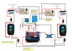
So on the attached image its the dotted black cable from the lynx.. what size???? (ac wiring isnt show obviously)
1619139194374.png
 
Are those Thermal circuit breakers from BlueSea/Eaton-Bussman or one of those $12 one from Amazon/Ebay?
 
This really is one of the hardest subjects to actually find answers to.. and nobody in any forum seems to be able to answer it.. can anyone show their setups? It may help to inspire me :)
 
Hi Guys - OK so not a solar question but one that seems to be evading google

I am installing a Multiplus 12/3000 240v. I have all the wiring done and am looking at the grounding side. Victron are vague on it, ABYC (im in aus so not relavent apart from reference) state that one size down from the main battery cable is acceptable. However on the diagrams on victrons site they show a ground wire going back to the negative bus bar (large) and then a ground going from that (no detail but appears small)

So i have a 120mm2 going from the case ground to the negative bus bar - thats fine. But as the house services power system (including inverter) are completely remote to the engines (main DC point) and mains AC point where is connects to the common DC ground, am i now assuming I have to connect the bus bar up to the common DC Ground? If so is it with 120mm2?

So on the attached image its the dotted black cable from the lynx.. what size???? (ac wiring isnt show obviously)

View attachment 46294
On a boat the grounds are common. All grounds should go to a main negative bus which is then connected to (in your case) each engine. There should not be 2 ground systems. The chassis ground should also go to the main negative bus and be no more than one size smaller than the main inverter DC cables. It is there for a DC fault and needs to be able to handle large currents.
 
On a boat the grounds are common. All grounds should go to a main negative bus which is then connected to (in your case) each engine. There should not be 2 ground systems. The chassis ground should also go to the main negative bus and be no more than one size smaller than the main inverter DC cables. It is there for a DC fault and needs to be able to handle large currents.

Thanks for that. So in place I have the negative bus, the case ground (120mm2) going to the negative bus, I know I have to return this negative bus back to the engines.. or boat common ground point, but the bit that has me stumped (and everyone else) is the size of the cable to do this. On my diagram its shown as a dotted black line from the lynx power in. Some say it should be sized for DC, others for AC.. Victron have nothing to say on the matter, and any info online is conflicting.

The reason for having 2 ground systems (DC) is that the batteries are remote from each other. The cabling required to run everything back to the engines would be silly, hence creating the 2 separate systems on the boat.. but I know they HAVE to be linked on the ground side.

Steve
 
That is a massive case ground. The largest common boat cable in North America is 4/0 which is 107mm2.

ABYC states that the case ground of an inverter should not be more than one size smaller than the main positive and negative cables to the inverter.

The size of the cables from the negative bus to the ground point, typically the engines, should not be smaller than the wires that go to the inverter. If they are smaller it defeats the reason to have large cables to the inverter.
 
Yep the cables to the inverter are a combination of 120mm2, copper bus bar and 95mm2 and i had some spare earth cable at 120mm2.. so used it. I'm in Aus so not under ABYC but use it as a guide anyway..

The size of the cables from the negative bus to the ground point, typically the engines, should not be smaller than the wires that go to the inverter. If they are smaller it defeats the reason to have large cables to the inverter.

Ok now this is the bit that has me confused. (the following is just my musings and probably wrong) Any DC fault will be going back to the battery... The inverter is connected to the Lynx Power in and that to the battery. Thats the only circuit that the DC fault can occur. So my question is why does the ground from the Lynx power in to the engine (say this is the ground point) have to cover the 300+amps? I dont mind running 95mm2 to the engine from the bus bar - I just want to understand why.. :) I understand the need for an earth cable to run back to the common earth (either in the DB or to the common ground) as this allows the RCD's to trip..

Steve
 
If there is an inboard engine then that is where the ground (negative) bus terminates. If the boat is outboard powered the ground bus terminates at the negative battery post.
 
Thanks, got a lot to learn.
Having a start battery and electric motor batteries in an aluminum boat I was not sure.
Charge controller is charging the house batteries only (electric motor). So I need to ground the house batteries to the outboard start negative also (Being the main buss bar)?
 
All battery grounds are common - regardless of voltage. They typically join at a busbar. From there to loads including engine.

The only unique thing about an aluminum boat is to make sure the hull and structure isn't connected to ground. If it has to be through the drive system that is the only place.
 
Have seen first hand what electrolysis will do to a out drive.
Thanks, very clear. With PV panels on board now was concerned about high volts leaching around swimmers.
 
All battery grounds are common - regardless of voltage. They typically join at a busbar. From there to loads including engine.

The only unique thing about an aluminum boat is to make sure the hull and structure isn't connected to ground. If it has to be through the drive system that is the only place.

i don’t agree with that idea.
At some point the boat ALWAYS is an anode which is why we use zincs to give something of higher potential the opportunity to sacrifice itself instead of the boat. Especially ignored with outboards but still...

The idea of bonding and zincs is so the boat /doesn’t/ have electrical potential in the water. Which is why DC power systems have home runs to common neg(-) busbars for example. That way you don’t have trace currents running willy nilly - you force them to behave or blow a fuse if the hull becomes a circuit.
What do you not agree with? The grounds being common? Or their connection to the engine(s).

If there is a leak to the hull from the negative you will not blow a fuse.
 
What do you not agree with? The grounds being common? Or their connection to the engine(s).

If there is a leak to the hull from the negative you will not blow a fuse.
I would see that all neg(-) from equipment get home run grounded to batteries or connected via bussbar then hopped to batteries. But I would also see to it that the boat hull (in a metal boat) was wire-grounded with a separate daisy-chain wire to the outboard mount casting or out drive which has fresh zincs. In this fashion a) the boat doesn’t see the level of corrosion that is typical and b) sometimes after adding this electrical problems “suddenly show up” and you can fix them (they probably always existed but aluminum corrosion masked the ‘leak.’ A third benefit is that if something bad happened to a wire it would be assured of blowing a fuse.
Too many boats are ‘accidentally’ grounded or - worse- people just use the hull for a ground. Both can create issues.

It’s basically impossible to not have an aluminum hull have a path to neg(-) o I prefer to control that by intentionally grounding the hull. I have been criticized robustly by some marine electricians over the years, ‘kudos’ by others. But even in plastic boats I’ve seen the helm rack’n’pinion arc to an accidental contact with a pos(+) that was live. And not blow the fuse. A ring terminal and some wire later it immediately blew the fuse.
I’ve seen tin tracing in the wood grain from a leaky bussbar in a wooden boat. The micro-current of assumably damp-conductive wood apparently drew some tin off the wires over time from the non-insulated buss to the helm mounting.

Electricity is a funny thing.
 
I would see that all neg(-) from equipment get home run grounded to batteries or connected via bussbar then hopped to batteries. But I would also see to it that the boat hull (in a metal boat) was wire-grounded with a separate daisy-chain wire to the outboard mount casting or out drive which has fresh zincs. In this fashion a) the boat doesn’t see the level of corrosion that is typical and b) sometimes after adding this electrical problems “suddenly show up” and you can fix them (they probably always existed but aluminum corrosion masked the ‘leak.’ A third benefit is that if something bad happened to a wire it would be assured of blowing a fuse.
Too many boats are ‘accidentally’ grounded or - worse- people just use the hull for a ground. Both can create issues.

It’s basically impossible to not have an aluminum hull have a path to neg(-) o I prefer to control that by intentionally grounding the hull. I have been criticized robustly by some marine electricians over the years, ‘kudos’ by others. But even in plastic boats I’ve seen the helm rack’n’pinion arc to an accidental contact with a pos(+) that was live. And not blow the fuse. A ring terminal and some wire later it immediately blew the fuse.
I’ve seen tin tracing in the wood grain from a leaky busbar in a wooden boat. The micro-current of assumably damp-conductive wood apparently drew some tin off the wires over time from the non-insulated buss to the helm mounting.

Whether to ground the hull or not is a debate. I prefer not to and it is easily done.
 
Back
Top