diy solar

diy solar

Grounding issue? Shorting

I’ll start with “I’m not a grounding expert “.
I think there is something that is obscure that’s causing the problem.
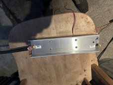
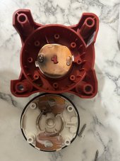
What is the aluminum I beam looking item on the inverter battery ground?
I wouldn’t connect the battery DC ground to the house AC ground. If something goes wrong with the house ground now you have AC on the battery system.
If you do it would need to be sized larger than the battery fuse so not to melt the ground wire.
The purpose of AC ground “chassis ground “ is if a device ( switch, motor, inverter) is if there is a internal short to the case there’s a path to ground that is a lower resistance than you if you touch the case. Also the chassis ground allows a path to develop enough amperage to trip the breaker.
The ground system should always look like a tree with its branches.
As far as the DC to the AC, I don’t know enough about that. It seems like the Electrician would know this, as he’s had some experience. He just doesn’t know a lot about systems like mine, but more commercial built systems.
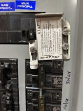
As far as the I-beam goes, battleborn says any inverter that does over 4000 W needs this surge type of protection. I believe it’s some kind of capacitor. The other photo is of my panel connection with 50 amp breakers. The AC out on the inverter goes to the panel. Using 6/3 gauge wire.
 

Attachments

  • 49C4CCF3-FD0E-4722-A447-1158ABFF5F72.jpeg
    49C4CCF3-FD0E-4722-A447-1158ABFF5F72.jpeg
    279.9 KB · Views: 9
  • 238B26B3-C577-403D-959D-E9FA89D8D1E9.jpeg
    238B26B3-C577-403D-959D-E9FA89D8D1E9.jpeg
    163.9 KB · Views: 9
It might have to do with the fact that I was in a hurry, after grounding it differently. I accidentally turned on the charge controllers first (even though it was dark), then I turned on the the cut off switch- then a flash happened at the 48 V cut off switch from batteries to busbar. I quickly turned off the charge controllers, but the damage may have already been done. I really don’t know, perhaps the ground wires work attach firmly enough.
Sometimes it’s better to leave things until the next day, instead of working on something for hours into the evening. ?
How long was the battery cutoff was in the off position to cut the power from battery to the load?
It sounds like the capacitor banks in the inverter were discharged then when you turn the cutoff switch to ON so the high inrush current occurs.
At this point i do not believe it is the grounding issue if all the chassis are all correctly grounded to the ground bussbar in the panel, ground wire is for fault current only and it is to provide the path of the fault current back to the source to trip the breaker.
 
How long was the battery cutoff was in the off position to cut the power from battery to the load?
It sounds like the capacitor banks in the inverter were discharged then when you turn the cutoff switch to ON so the high inrush current occurs.
At this point i do not believe it is the grounding issue if all the chassis are all correctly grounded to the ground bussbar in the panel, ground wire is for fault current only and it is to provide the path of the fault current to trip the breaker.
I believe it was an hour or longer, as I had to re-wire connections from charge controller to charge controller. Strange that the batteries fuse didn’t blow then?
Basically right now I have all three charge controllers grounded to a small ground bar that goes to a separate ground bar in the backyard. Remember, this is separate from the inverter that’s going to the panel ground.
My problem is, I don’t know how to ground the charge controllers without doing it this way, I can’t find any information on how to ground the charge controllers except by daisy-chaining to the inverter or hooking them to the negative busbar? They do this on vans, were the only place I’ve seen how it works.
 
Last edited:
I believe it was an hour or longer, as I had to re-wire connections from charge controller to charge controller.
Basically right now I have all three charge controllers grounded to a small ground bar that goes to a separate ground bar in the backyard. Remember, this is separate from the inverter that’s going to the panel ground.
My problem is, I don’t know how to ground the charge controllers without doing it this way, I can’t find any information on how to ground the charge controllers except by daisy-chaining to the inverter or hooking them to the negative busbar? They do this on vans, were the only place I’ve seen how it works.
Don’t ground anything to neutral , start with that. Don’t ground the invertor output neutral.
 
Don’t ground anything to neutral , start with that. Don’t ground the invertor output neutral.
The inverter is grounded by a green wire to panel. I do hear that on main panels that you can ground to both neutral and ground, but on subpanels you cannot. All charge controllers grounds are going to a separate ground bar outside.
 
Last edited:
BTW, I look at the user manual and it shows that it has relay for bonding N to G (PE) when it is in the inverter mode.
The manual does not say if that function can be enable/disable or not.
1668656365997.png
 
Do I wire them down to the negative bus bar, because right now I have them wired to a separate ground bar that goes outside.
Both neutral and ground need to be wired to the same ground (buss bar in the panel). Look up "ground loop". Also, make sure the ground wire is thick enough (thin wire could have a voltage difference between the equipment and the panel).
 
Both neutral and ground need to be wired to the same ground (buss bar in the panel). Look up "ground loop". Also, make sure the ground wire is thick enough (thin wire could have a voltage difference between the equipment and the panel).
Yes, the electrician understood that I’m sure. That’s why I have 6/3 gauge wire connected from inverter to panel ground/neutral. I just meant I don’t understand diagrams.
 
I read through this and noone mentioned one important detail, GFP (Ground Fault Protection) and it sounds like that is the culprit here. I am unsure how Victron deals with that, best check your documentation.

I use Midnite Solar Classic SCC (Has GFP circuitry), Midnite E-Panel and Samlex EVO Inverter with intelligent ATS to switch between AC Sources (has GFP support). My AC System is grounded to my Well Casing and the DC is handled through the E-Panel.

On your Inverter subsystem, do you have a Neutral Bonding Circuit/wire which bonds the Neutral to the Inverter Chassis and subsequently to the AC Ground (Generator or grid input AC). This is to support either Mobile (RV/Marine) or stationary Land installation with grid/generator input.

OOPS, Failed to mention, lesson learned "the hard way".
Some cheap CGFI Plugs can & do wreak havok and can trip inverters ! My well Pump is on a CGFI Plug (it's 120V) and I went through 3 before I got a good one from Eaton, bathroom circuit is on a Square-D CGFI Breaker and no issue with that one.
 
Last edited:
I read through this and noone mentioned one important detail, GFP (Ground Fault Protection) and it sounds like that is the culprit here. I am unsure how Victron deals with that, best check your documentation.

I use Midnite Solar Classic SCC (Has GFP circuitry), Midnite E-Panel and Samlex EVO Inverter with intelligent ATS to switch between AC Sources (has GFP support). My AC System is grounded to my Well Casing and the DC is handled through the E-Panel.

On your Inverter subsystem, do you have a Neutral Bonding Circuit/wire which bonds the Neutral to the Inverter Chassis and subsequently to the AC Ground (Generator or grid input AC). This is to support either Mobile (RV/Marine) or stationary Land installation with grid/generator input.

OOPS, Failed to mention, lesson learned "the hard way".
Some cheap CGFI Plugs can & do wreak havok and can trip inverters ! My well Pump is on a CGFI Plug (it's 120V) and I went through 3 before I got a good one from Eaton, bathroom circuit is on a Square-D CGFI Breaker and no issue with that one.
I believe the ground fault protection was in place, as the electrician would’ve tied the ground to the neutral/ground at the main panel. If it’s already grounded there, where am I supposed to ground the chassis of the inverter? Attachment enclosed. ?
 

Attachments

  • 342D7F6D-3ECC-4CB5-B1AE-5FA6D7E6FB49.jpeg
    342D7F6D-3ECC-4CB5-B1AE-5FA6D7E6FB49.jpeg
    247.4 KB · Views: 7
YES, that should be to the common ground. There would be a QD (Quick Disconnect) wire or jumper inside the inverter for bonding. BUT I do not use Victron by Samlex which has this feature but as a Tier-1 product Victron should also have such, even many "Value" inverters do as well, as it depends if it is mobile (RV/Marine) or not.

There are far too many electricians who handle AC but are clueless about DC Systems and there are significant differences which they are unaware of.
Yes, but where does or does there need to be a ground wire connected here? If you already have it grounded at the main panel. Also, where do the grounds go on the charge controllers, nobody seems to be able to answer this?
I have all my charge controllers, going to a ground rod outside, but doesn’t this defeat, the purpose of having it already grounded at the main? I want this cause, a loop that is dangerous!
I’ve seen on vans, that you ground all your equipment to your negative bus bar, and then ground your car chassis. ?
 
Correct, vehicles are isolated from physical ground because Rubber is one hell of an insulator. LOL.
The Inverter ground lug is grounded to the common AC Ground, such as in my installation. PS I have no grid up here.
My SCC is grounded with the Midnite Solar E-Panel (MNDC-250)

I have ONE AC Ground which is my well casing (6" casing, 24' deep, sealed into the granite bedrock).
All AC Circuitry is Bonded together per regs.
My Solar Panels and aluminium Rails they are attached to is 45' away from the powerhouse and grounded to a ground plate 3' deep & 3' from the wooden ground mount for Lightning safety.
NONE of my battery Negatives are grounded as that is handled up line.
Sounds like you’re totally off grid! I would love to get there, but I am depending on gas to heat my home, as solar is no good in the Pacific Northwest at least for 24x7 in the winter.
 
Sounds like you’re totally off grid! I would love to get there, but I am depending on gas to heat my home, as solar is no good in the Pacific Northwest at least for 24x7 in the winter.
chuckle chuckle... I am in North Eastern Ontario Canada near Algonquin Park. My Sun Hours get pretty low as winter progresses.
 
Update: looks like the inverter isn’t the problem, as it says, low voltage battery on the red light.
Message from battleborn.
I connected with a group of Senior Techs that I worked with, and they shared that if a 48v 5000 Quattro was “fried” it wouldn’t work at all. A good thing with Victron devices is that they either function or do not. So the fact that yours turns on is a really good sign – we just have to look to see why it shuts off. Do you have extra battery cable where you can go from the positive of the battery bank where you are coming off directly into the inverter?
I have to run some more tests, going straight from the positive battery and negative battery to the inverter.
We are starting to believe that one of your inline fuses is shot or close to failing causing heavy resistance which is causing an inrush shutting the batteries off.
 

Attachments

  • D3D16063-478B-47DD-974A-188C73A10535.png
    D3D16063-478B-47DD-974A-188C73A10535.png
    1.8 MB · Views: 3
Update: looks like the inverter isn’t the problem, as it says, low voltage battery on the red light.
Message from battleborn.
I connected with a group of Senior Techs that I worked with, and they shared that if a 48v 5000 Quattro was “fried” it wouldn’t work at all. A good thing with Victron devices is that they either function or do not. So the fact that yours turns on is a really good sign – we just have to look to see why it shuts off. Do you have extra battery cable where you can go from the positive of the battery bank where you are coming off directly into the inverter?
I have to run some more tests, going straight from the positive battery and negative battery to the inverter.
We are starting to believe that one of your inline fuses is shot or close to failing causing heavy resistance which is causing an inrush shutting the batteries off.
Update: I found the problem or at least I think I did, until I get a replacement I won’t know for sure!
Pictures enclosed.
Also, this guy has taken all the courses at Victron and become certified and talks about this issue! Apparently these things are’nt safe for 48 V. Five minutes and 30 seconds into the video you can hear him talk about it. ?
 

Attachments

  • 5C8FF8A3-0661-4A97-953A-79EE397146D9.jpeg
    5C8FF8A3-0661-4A97-953A-79EE397146D9.jpeg
    91 KB · Views: 4
  • 9E418A51-C885-4B40-8F08-0FC9C0D252C8.jpeg
    9E418A51-C885-4B40-8F08-0FC9C0D252C8.jpeg
    131.2 KB · Views: 4
Last edited:
That’s why I have 6/3 gauge wire connected from inverter to panel ground/neutral.
6/3 wire is three #6 insulated wires in a common insulated jacket. 6/2 with ground is two #6 insulated wires plus a #6 non-insulated wire in a common insulated jacket. I'm guessing you have just a #6 wire connecting your inverter to your panel ground. It is OK for your bonding wire to be bare (not insulated).

In general, you want to bond all of the chassis "ground" lugs to your ground wire that leads to your ground rod. Don't bond other things to the ground wire, except...

The AC neutral line can only connect to that ground wire at one place, which would normally be your distribution panel. If the inverter does it already, don't do it again.

For a stationary system with a ground rod, don't connect the battery negative to the ground wire. In a vehicle system with no ground rod, bond the battery negative to the chassis.

Apparently these things are’nt safe for 48 V.
I take it that you are talking about your Blue Sea switch. It has current ratings that are clearly stated on the front bezel. As someone already mentioned, you must control the inrush current when you connect your battery to your inverter. I use a 100W light bulb as a shunt resistor to limit the current during first contact, then add the battery positive after the inrush is over.
 
Update: I found the problem or at least I think I did, until I get a replacement I won’t know for sure!
Pictures enclosed.
Also, this guy has taken all the courses at Victron and become certified and talks about this issue! Apparently these things are’nt safe for 48 V. Five minutes and 30 seconds into the video you can hear him talk about it. ?
Looks like I spoke too soon, as I got all the new components, including the battery switch and installed them and still the same problem? I would say it’s even worse as now I can’t even get my charge controllers to light up.
The problem is, I can’t get the right voltage reading from the battery switch to the positive bus bar?
Update: I replaced the positive wire at the battery switch and that solved the voltage problem. Unfortunately, when I connect the fuse to the inverter is still shut down the batteries? I’m going to try to replace the positive wire on the inverter and see if that does anything, as I’m quickly running out of any ideas. I even took off the ground for the charge controllers, and it made no difference whether it’s on ground or off ground. ?
Switched the wire out for the inverter and nothing improved. I did turn on the inverter before I turned on the battery switch and the red low battery light showed on. The shunt seems to be OK, so I’m not sure if I should replace that or not.
Perhaps the CSL from Battle Born Batteries is damaged, but that’s on the negative side?
I’m out of ideas! ?
 
Last edited:
Back
Top