diy solar

diy solar

Grounding Question

garyp1961

New Member
Joined
Mar 19, 2022
Messages
20
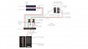
Solar wire.pngHi,
I am adding a separate main panel for my house that will be on solar only. I plan to move the circuits over to the solar panel (including the hot, neutral and ground) that way they will not be tied into the grid panel at all. My question is how would I ground this system. I have 2 x EG4 6500 EX inverters with
4 x EG4 48V 100AH 5.12KWh batteries. I have also included a diagram of how it will be wired for any feedback or suggestions. Thank you for your help
Gary
 
Subpanel would ground to the main panel ground, no N-G bond would be made in the subpanel, since the EG4 supplies an N-G bond (is closer to power source), while inverting (turned on).

Similar to the MPP Solar LV6548 (EG4 6500EX looks like similar clone), it is known with those, that you need to break the N-G bond (remove screw inside it) on one of the inverters since you are not supposed to have more than one power source with N-G bonded. Also can create some power bleed through the ground between the two (enough to trigger ground fault detection I've heard).

Check out this video for some reference:

We also know that this style inverter only bonds N-G inside it when inverter is turned on, but when the inverter is turned off (in bypass), a relay in each inverter opens the internal N-G bonds (so that the N-G bond is then being provided by the upstream AC grid power panel.

Seems the solution they found was to remove a screw in one of the inverters (like the slave one), which permanently breaks the N-G bond in one of the 2 inverters (so there is only one bond)...

I still haven't installed my LV6548s yet so I have only read all the threads on this and haven't actually experienced any of the issues first hand some people have found here. But basically the NEC states that there should only be one N-G bond, as close to the power source as possible, so in the case of the input AC grid panel, just leave that N-G bond as normal (since it is more the power source seeing the inverters as an appliance (for pass-thru and grid battery charging) when inverters are in bypass, and then when inverters are turned on (inverting), only one of the inverters should be providing the N-G bond, and all the other ones disabled (by removing the N-G bond screw in them)...
 
Here's some more info about it as well (with an MPP Solar, which is very similar to the EG4):

 
Thank you, I am not using grid power at all and I am pulling all the wires for the circuits that I want to use for solar from the main panel which will include the (hot, neutral and ground) since I am not using the main house panel for any part of the new solar panel would I need to install a new ground to earth for the new solar panel?
 
Thank you, I am not using grid power at all and I am pulling all the wires for the circuits that I want to use for solar from the main panel which will include the (hot, neutral and ground) since I am not using the main house panel for any part of the new solar panel would I need to install a new ground to earth for the new solar panel?

You just don't want 2 Earth-ground paths in the one structure (well, unless they are connected together outside with a bridge cable at worse case). So usually you figure out where is your power source, in this case, the inverters (have them connect to main ground pole, I would use a feeder panel upstream), where one of those inverters has the one N-G bond, and there should be no other dual paths to Earth-ground, and no other N-G bonds. It keeps the ground and the neutral separate for the most distance in any house circuit all the way back to the power source.

So then when you install your AC output breaker panel, you would remove the N-G bond connector plate or screw in there (since one of the inverters (the master) would have the N-G bond made there (upstream), assuming you take out the N-G bond screw from the slave inverter...
 
I understand thank you so much for your help Samsonite801, also did you see anything wrong with the wire diagram or does it look ok? Wire size and all?
 
I understand thank you so much for your help Samsonite801, also did you see anything wrong with the wire diagram or does it look ok? Wire size and all?

Sure no prob at all...

On the diagram, in fact I saved your picture earlier tonight, because I'm helping a fellow shareholder at our co-op to wire/install their EG4 6500EXs in their storage container, and I had been trying to explain to them about what the wiring looks like (drawing it on paper with my horrible sketching), so I saw yours and thought I could use it to show to them so they can get a better idea on how it all should look in the end. Only difference is theirs can only go 8s in series but nearly identical.

I'd personally like to go 8 AWG on the solar PV cable, but 10 AWG is considered fine in this application (with higher volts, lower amps).

2/0 should be fine on battery cables (main run), unless length is too long...

4 AWG is fine on the AC feeds, goes good with the 60a breaker.
 
Last edited:
haha ok, if you need anything changed just do it on my drawing and I will edit it and link it here. Canva saves a copy so I can do anything with it.
 
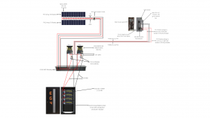
@Samsonite801 How does this look with the grounding wires run now?

I like the idea there... Is that conduit between the AC grid panel and the solar system output panel metal? If so it would create a ground loop?

I would also look into installing some Midnite Solar surge protectors on the PV runs... They can go near the panel, they have ground connections and can go to their own grounding rod out by the array (as it is an isolated ground, only invoked for surge power exceeding the threshold voltage running across the PV conductors).

Also, the latest word (that I've learned anyways) is to not ground the actual solar array chassis, as it could attract lightning to it. I have thought of using a resistor instead to lightly ground the array chassis, so it is not a 0 Ω ground, just to keep static electricity potential down (like from wind). I am toying around with the possibilities still.

I used 300v surge arrestors on mine, but they make 600v ones too:
 
Last edited:
I like the idea there... Is that conduit between the AC grid panel and the solar system output panel metal? If so it would create a ground
Thank you for that advice. Would using insulated green thhn #4 wire work and prevent grounding issues?
I will also look into the surge protection as well that's a really good thing to have.
 
Thank you for that advice. Would using insulated green thhn #4 wire work and prevent grounding issues?

Sure no prob..

It could help to have insulated ground wire in certain places. But need to make sure that if the grounding bus bars (and ground wires in the box) in the two boxes are not insulated from touching the case/box, then a metal conduit will ground the 2 boxes together, in effect making a shorter ground path to the ground rod, and not travel through the inverter where N-G are joined (since the solar output breaker box is operating as a 'subpanel' to the power source, the inverter).

You basically want to make sure the ground path goes as far as it can, closest to the the power source where the N-G bond is, then shortest path from there to ground rod, with no ground loops.
 
Last edited:
Sure no prob..

It could help to have insulated ground wire in certain places. But need to make sure that if the grounding bus bars (and ground wires in the box) in the two boxes are not insulated from touching the case/box, then a metal conduit will ground the 2 boxes together, in effect making a shorter ground path to the ground rod, and not travel through the inverter where N-G are joined (since the solar output breaker box is operating as a 'subpanel' to the power source, the inverter).

You basically want to make sure the ground path goes as far as it can, closest to the the power source where the N-G bond is, then shortest path from there to ground rod, with no ground loops.
I could just move the hot and neutral wires from the main house panel to the solar (subpanel) and leave the grounds in the main panel and not move them to prevent grounding issues. Would that work better?
 
I could just move the hot and neutral wires from the main house panel to the solar (subpanel) and leave the grounds in the main panel and not move them to prevent grounding issues. Would that work better?

Not sure I'm totally following what you're describing there for sure. But the main panel (AC grid input) and the subpanel (solar inverter AC output) shouldn't be tied together at all (if fact should be isolated completely, except for what's going through the inverter). Unless you had some type of temporary ATS bypass breaker (not sure if you are going to do this, but the inverters have their own bypass method, as in ATS built-in). Then when the inverters would be in bypass, then the master inverter will unbond N-G there, but the ground will still follow from the subpanel through the inverter ground and back to the main panel ground where it is N-G bonded there (it being the present power source during bypass)...
 
Last edited:
Not sure I'm totally following what you're describing there for sure. But the main panel (AC grid input) and the subpanel (solar inverter AC output) shouldn't be tied together at all (if fact should be isolated completely, except for what's going through the inverter). Unless you had some type of temporary ATS bypass breaker (not sure if you are going to do this, but the inverters have their own bypass method, as in ATS built-in). Then when the inverters would be in bypass, then the master inverter will unbond N-G there, but the ground will still follow from the subpanel through the inverter ground and back to the main panel ground where it is N-G bonded there (it being the present power source during bypass)...
I wouldn't have them tied together at all. Only the ground wires. I would move the circuits I want over to the solar panel with the hot and neutral of that circuit and just leave the ground at the main panel. I hope I'm explaining this correctly.
My goal was to have two separate panels with one panel being fed from the grid for the heavier loads, and I was going to move all the 120v circuits over to the solar panel. I would move the hot and neutral wires for each circuit and leave the grounds back at the main. Would that be feasible?

Except that NEC wants you to have N-G bonded at the power source (which is closest to the inverter Hot and Neutral outputs), and the ground paths should be separate from neutral, and direct, all the way back to where the N-G bond is made (closest to the power source as possible). You really need to move all the wires you want to migrate over, Hot, Neutral, and Ground to the inverter loads panel. And that whole panel grounds only through the inverter and all conductors feed back through inverter, and to the main panel ground, and to the ground rod.

The rule on grounding (according to NEC).... We need the ground to go, not to the ground rod being the source, but to the actual power source (the return for the neutral at the N-G bond), the ground rod connection is only there to help hold ground to a reference, as in Earth ground reference, but the power source is the return (through neutral at the N-G bond) that a faulted circuit is looking to return to, not the Earth ground itself. When a circuit faults, the goal is to return the current to the power source (inverter output neutral), so that a short to ground through the chassis of a household appliance will be enough current to trip the breaker and diffuse/deactivate the fault (removing the shock danger).

So the inverter needs to be the only gateway/path for all connections to the inverter loads panel.
 
Last edited:
Back
Top