diy solar

diy solar

Growatt 3000 SPF Floating Neutral (Solved for Now)

Not sure what I was doing wrong previously, but it worked fine the second time around. Getting it in to AC bypass mode allowed me to test if there was any current on the incoming Ground cable.

With around 7A on the incoming Neutral cable, there was 0.01A on the Ground cable.

So, with the firmware version that I have, the Growatt SPF5000ES appropriately creates the N/G bond in battery mode, and removes the N/G bond in AC bypass mode.

(I imagine this is why I've seen some people mention a firmware update broke the "external N/G bond relay" functionality - it's done internally now)

I've linked a copy of my finalised AC wiring for the installation.

I must stress, by the sounds of what others have posted, this functionality is dependant on what firmware version you have. So updating the firmware seems a fairly important step for this inverter.

View attachment 81118
Thanks for that info!!!! I will add it to my document. Do you have the P/N that is on the nameplate on the inverter?
 
I have taken a photo of one dataplate (the above installation is a parallel installation with 2 inverters and single phase output)

The PN is: SKSL00.0009001. My units are SPF5000ES (48V).

edit: I want to stress, I'm from Australia. Hopefully there aren't fundamental differences between inverters sold in different areas. So when using these inverters, please test test test.

edit2: And from my reading of a different Growatt thread, the safety issues that are explained above, are completely different in a system with an autotransformer installed. My advice is do not follow the advice in this thread if you have an autotransformer involved in your installation.

Those edits seem fair @FilterGuy ?
 
Last edited:
I want to stress, I'm from Australia. Hopefully there aren't fundamental differences between inverters sold in different areas. So when using these inverters, please test test test.
Yes. The concepts are similar worldwide, but the standard practice and rules for how to implement things changes from country to country.
It is important to understand the concepts *and* understand how it is done in your country.

And from my reading of a different Growatt thread, the safety issues that are explained above, are completely different in a system with an autotransformer installed. My advice is do not follow the advice in this thread if you have an autotransformer involved in your installation.
Yes. Autotransformers are a place where differences between countries can create significant safety issues. Specifically, the Split phase system used in North America has a very different definition of neutral than in the rest of the world. Trying to mix systems with the North American definition of neutral and the rest-of-world definition of neutral can be very problematic.

The main message is that grounding and bonding are not near as simple as a lot of people think. It is important to put in the effort to understand the concepts as well as the standard practice for your country.
 
Thanks for that info!!!! I will add it to my document. Do you have the P/N that is on the nameplate on the inverter?
just to confirm my point above, I took videos with my multimeter testing both continuity and voltage on the output N and G terminals, and when I switched from battery mode, to grid bypass, you could clearly see when the relays click in, the neutral-ground bond is removed.

when in battery mode, the resistance was 0 ohms and voltage was 0.00 V (indicating an N-G bond very close to the output terminals on the inverter), and in grid bypass, the continuity increased, and the voltage was consistent with what I would expect for an N-G bond that was 20+m away. the voltage between N-G in grid bypass was 0.33v.

I must stress, this is on the Growatt SPF5000ES in Australia.
 
Read through several posts on here regarding this inverter and grounding. Im noticing an odd behavior when im using the neutral bonding.

I essentially have an ADU that is my home office. Im tied to grid via my house, which has a N/G bond at the service panel. The inverter has separate G/L/N back to the house main panel. When neutral is bonded between input and output I notice that im importing more power than i'm using. For example I may be importing ~450 watts, but I'm only using ~230watts with the battery float charging at 47watts. I do not have option 24 on my inverter. I went ahead and removed the bond and now the import adds up correctly.
 
Last edited:
Read through several posts on here regarding this inverter and grounding. Im noticing an odd behavior when im using the neutral bonding.

I essentially have an ADU that is my home office. Im tied to grid via my house, which has a N/G bond at the service panel. The inverter has separate G/L/N back to the house main panel. When neutral is bonded between input and output I notice that im importing more power than i'm using. For example I may be importing ~450 watts, but I'm only using ~230watts with the battery float charging at 47watts. I do not have option 24 on my inverter. I went ahead and removed the bond and now the import adds up correctly.
are you saying you manually bonded the incoming neutral with the outgoing neutral?

I think we established through the thread that's not needed any more.

we started off thinking it might be, but it turns out because it creates it's own NG bond in battery mode, it's not needed.

if you are only using this inverter for 240v, you shouldn't need to do any manual bonding - this inverter is set up to handle 240v loads correctly.
 
BTW: I assume you have already looked at the back of the unit for the nameplate.
By any chance, do u know whether SPF 3000K-LVM ES Input and Output neutrals are tied together? And whether it will do the dynamic
NG bonding internally? Thanks
 
By any chance, do u know whether SPF 3000K-LVM ES Input and Output neutrals are tied together? And whether it will do the dynamic
NG bonding internally? Thanks
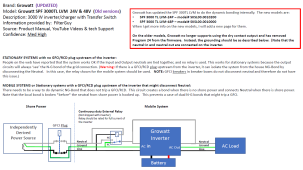
This is the latest info I have on that model

1654580767653.png

As you can see by the note, older versions work differently than newer versions. Unfortunately, I have not been able to confirm the behavior of the newer version, but presumably, it will generate an N-G bond when in inverter mode but not when it is in pass-through mode.
 
Thank you very much for taking the time for writing the 4 part papers on N-G bonding.

I am not an electrician but an engineer. I had residential wiring training & studied the 2002 NEC and rewired my garage 10 years ago. Just finished taking a solar energy tech class without the lab as it wasn't offered this semester. Hoping my questions make sense asking.

The Stationary System covered on your paper is not grid-tie, correct? On page 12, the figure was drawn beautifully! The Grid Interactive Inverter referred to is also not a grid-tied inverter, correct? It is grid interactive, meaning, it accepts utility/grid AC input , correct?

I also have some confusion on the term AC that come out on the paper. Since the inverter covert DC to AC and there is also an AC input from utility , I had trouble associating them. On page 5, the sub panel on Fig 2, referred to is a distribution panel or load center is not a sub panel that tapped the AC input, correct? The same question applies to Fig 1 &2 on page 15 as well. The systems drawn on page 5 and 15 are standalone type and not grid- interactive system, correct?
 
The Stationary System covered on your paper is not grid-tie, correct? On page 12, the figure was drawn beautifully! The Grid Interactive Inverter referred to is also not a grid-tied inverter, correct? It is grid interactive, meaning, it accepts utility/grid AC input , correct?
terms have gotten muddled over time.
Grid Interactive is almost always used to mean the inverter pumps power back on the grid.
Grid tie used to mean the same thing, but it is now often used for hybrid inverters that only take power from the grid. Perhaps a better term for an inverter that only takes power from the grid would be Grid Assisted inverter.

On page 12 I am referring to an inverter that puts power back on the grid.

I also have some confusion on the term AC that come out on the paper. Since the inverter covert DC to AC and there is also an AC input from utility , I had trouble associating them. On page 5, the sub panel on Fig 2, referred to is a distribution panel or load center is not a sub panel that tapped the AC input, correct?
correct. Both figure 1 and 2 show inverters that do not have AC input. The breaker box is just for distribution of the power coming out of the inverter.
 
The systems drawn on page 5 and 15 are standalone type and not grid- interactive system, correct?
Correct.

Keep in mind that Grid interactive almost always refers to inverters that pump energy back onto the grid.

Inverter-charger almost always refers to inverters that can connect to the grid to take power for powering the output and charging the batteries but never puts energy back on the grid. These will typically have an internal transfer switch that will automagicly switch between inverter mode and passthrough mode.

An all-in-one is an inverter-charger that also has one or more solar charge controller built in.

As I said earlier the term 'grid tied' has become muddled. It used to be the same as grid interactive, but now the term is also used for AIO inverters that do not put power back on the grid.
 
terms have gotten muddled over time.
Grid Interactive is almost always used to mean the inverter pumps power back on the grid.
Grid tie used to mean the same thing, but it is now often used for hybrid inverters that only take power from the grid. Perhaps a better term for an inverter that only takes power from the grid would be Grid Assisted inverter.

On page 12 I am referring to an inverter that puts power back on the grid.


correct. Both figure 1 and 2 show inverters that do not have AC input. The breaker box is just for distribution of the power coming out of the inverter.
Yes. The terms used depends on whose book you are reading.

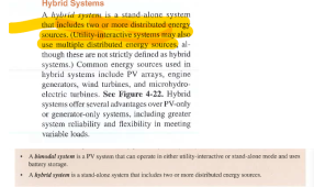
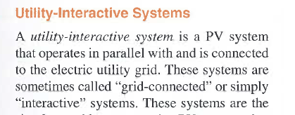
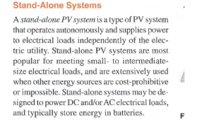
Here are some definitions from James P. Dunlop -Phtovoltaic System. It is a good book but it is 12 years old, new technology hasn't evolved.
1654807033970.png
1654807075662.png
1654807106122.png
 
As I said earlier the term 'grid tied' has become muddled. It used to be the same as grid interactive, but now the term is also used for AIO inverters that do not put power back on the grid.
It's up to us to keep it straight.
And correct people when they use the incorrect terms.
 
I fully agreed with not grounding the panel as said:
1654808060114.png
When panels are mounted on a steel frame structure, use of a grounding electrode is simply redundant.
 
Last edited:
Industry standards, is correct.
People who don't know any better, is incorrect.
 
To add confusion, I am installing a Growatt 3k LVM 48p on a houseboat. I also had issues with reverse polarity light coming on when inverting and discovered 59vac between neutral and ground. This unit was shipped to me in May 2022. I called Signature Solar 2 weeks ago and they reassured me that it NG bonded internally. After finding this thread it appears that some do and some don't. I don't have option 24 in the menu and I plan on implementing the neutral jumping and bonding relay as described by @FilterGuy. I put a call back to Signature Solar to confirm my Growatt could handle jumping the AC neutrals and he told me they tested one of their Growatts last week and found it did not internally bond NG. He also said not to bond the AC neutrals. I am waiting for a response from their electrician via email on this as I assume it is a different person than the guy I spoke with on the phone. I have a question....If I implement the wiring diagram @FilterGuy recommends for a mobile scenerio would that potentially give me 2 grounding points if shore power is lost but still plugged in? One from the grid and the other being the engine/outdrive on the boat? Would this create a ground loop and is it even a problem if it does?
 
To add confusion, I am installing a Growatt 3k LVM 48p on a houseboat. I also had issues with reverse polarity light coming on when inverting and discovered 59vac between neutral and ground. This unit was shipped to me in May 2022. I called Signature Solar 2 weeks ago and they reassured me that it NG bonded internally. After finding this thread it appears that some do and some don't. I don't have option 24 in the menu and I plan on implementing the neutral jumping and bonding relay as described by @FilterGuy. I put a call back to Signature Solar to confirm my Growatt could handle jumping the AC neutrals and he told me they tested one of their Growatts last week and found it did not internally bond NG. He also said not to bond the AC neutrals. I am waiting for a response from their electrician via email on this as I assume it is a different person than the guy I spoke with on the phone.
The way Growatt has mishandled this is unforgivable!!!! They made a fundamental change to the product and 1) Did not change the model number and 2) Did not notify distributors and customers. Attached is an email thread I had with the US Growatt support team. If you read through it they explicitly state they changed the product to do the bonding internally and to jumper the neutrals on the older versions.

Feel free to forward the document to Sig solar.
I don't have option 24 in the menu and I plan on implementing the neutral jumping and bonding relay as described by @FilterGuy.
Not having Option 24 means you have the new firmware, but it does not tell you if it is the new hardware. The first thing you should do is to check the continuity between Neutral and Ground when the inverter is completely disconnected. If you find continuity (as others have), then there is clearly a G-N bond and you have the newer version. With the newer version, you should *not* do the relay and Neutral jumper.

If I implement the wiring diagram @FilterGuy recommends for a mobile scenerio would that potentially give me 2 grounding points if shore power is lost but still plugged in? One from the grid and the other being the engine/outdrive on the boat? Would this create a ground loop and is it even a problem if it does?
So people reading the thread can see what we are talking about, here is the circuit.

1655410793705.png

As mentioned above, this should NOT be implemented if you have the new version of the hardware.

I probably should have indicated earth grounding in the picture. Perhaps this is better:
1655411465764.png

Either way when plugged in but no power, there will be no neutral connection between the AC Source and the Growatt so there will not be two NG bonds. Furthermore, there are no loops in the Equipment Grounding conductor.
 

Attachments

  • Ginverter email re NG bond on growatt.pdf
    155.9 KB · Views: 14
Back
Top