diy solar

diy solar

Growatt 3000 SPF Floating Neutral (Solved for Now)

@FilterGuy, your contribution has been extremely helpful! I will be working on this tomorrow and will update with my findings, model number, etc. Curious to see if the model numbers do correlate with what they have told you. Thanks again!
 
To add confusion, I am installing a Growatt 3k LVM 48p on a houseboat. I also had issues with reverse polarity light coming on when inverting and discovered 59vac between neutral and ground. This unit was shipped to me in May 2022. I called Signature Solar 2 weeks ago and they reassured me that it NG bonded internally. After finding this thread it appears that some do and some don't. I don't have option 24 in the menu and I plan on implementing the neutral jumping and bonding relay as described by @FilterGuy. I put a call back to Signature Solar to confirm my Growatt could handle jumping the AC neutrals and he told me they tested one of their Growatts last week and found it did not internally bond NG. He also said not to bond the AC neutrals. I am waiting for a response from their electrician via email on this as I assume it is a different person than the guy I spoke with on the phone. I have a question....If I implement the wiring diagram @FilterGuy recommends for a mobile scenerio would that potentially give me 2 grounding points if shore power is lost but still plugged in? One from the grid and the other being the engine/outdrive on the boat? Would this create a ground loop and is it even a problem if it does?
I have the 48V ES Model didn't you? Mine, the N-G on the output terminals were bonded. Mine is set up as a stationary unit and I use Grid AC input. My N-G is already bonded in my Main 200A Service Panel.

It is very confusing to me as well to this date as I think my unit (ordered in May 2022) should not have N-G bonded together in the output terminals. I just think it should have the Neutral terminals bonded together to work for a stationary system. Because doing that (since I have the bond in the Service Panel) could create another ground loop that will not trip the circuit breaker in case of a ground fault.

For mobile system not using a grid input, I think the N-G bond should be required. But you will need the ground wire to a Ground rod. I was thinking of discussing my stationary system with FilterGuy on that.

Whose know what the new firmware do inside , it may just do the magic to undo something to make it work.

I think we should let FilterGuy help contacting Growatt as I believed he got the right person to talk to. If you contact them you may get another guy who is not so knowledgeable.

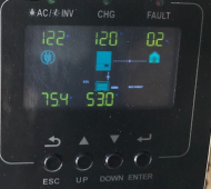
I just hook up my stationary system an hour ago and it seemed to be working fine even I felt the N-G should not be bonded. I used an outlet tester and showing no fault. I tried running a hairdryer and was running good. Without load, the idle consumption on the Inverter is 0.2W as shown below.
1655416621876.png
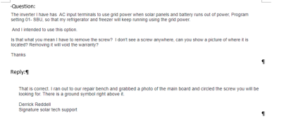
To add to my confusion, I just received a follow-up email I sent out a week ago from Signature Solar, the tech guy said I need to remove the bonded screw for my stationary unit. I am not doing that now.

I want to send a Report Card to FilterGuy to look at it.
Hey FilterGuy, here is my report card attached.
 

Attachments

  • Report Card 6-16-2022.pdf
    3 MB · Views: 19
@FilterGuy, your contribution has been extremely helpful! I will be working on this tomorrow and will update with my findings, model number, etc. Curious to see if the model numbers do correlate with what they have told you. Thanks again!
Haven’t looked at this thread for a while. What is the go-to firmware for the 3000TL LVM-48P these days. Mine has been humming for months with 10kwh of lifepo4. Will also get picture of my model number. I have the neutrals tied as that was the resolution at that point in time. Never was able to get this tied to a reliance transfer switch which was my ultimate backup goal. Just have grid/PV input and ac out to a circuits that has a few small lights and two refrigerator/freezers.
 
The way Growatt has mishandled this is unforgivable!!!! They made a fundamental change to the product and 1) Did not change the model number and 2) Did not notify distributors and customers. Attached is an email thread I had with the US Growatt support team. If you read through it they explicitly state they changed the product to do the bonding internally and to jumper the neutrals on the older versions.

Feel free to forward the document to Sig solar.

Not having Option 24 means you have the new firmware, but it does not tell you if it is the new hardware. The first thing you should do is to check the continuity between Neutral and Ground when the inverter is completely disconnected. If you find continuity (as others have), then there is clearly a G-N bond and you have the newer version. With the newer version, you should *not* do the relay and Neutral jumper.


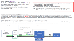
So people reading the thread can see what we are talking about, here is the circuit.

View attachment 98855

As mentioned above, this should NOT be implemented if you have the new version of the hardware.

I probably should have indicated earth grounding in the picture. Perhaps this is better:
View attachment 98865

Either way when plugged in but no power, there will be no neutral connection between the AC Source and the Growatt so there will not be two NG bonds. Furthermore, there are no loops in the Equipment Grounding conductor.
I hookup my system and had sent your the report card. Seemed like working fine.
Here is the confusion Solar Signature sent me.
1655417878259.png
 
I am pretty sure mine is not NG bonding internally. I will verify tomorrow. Can I buy that magic bonding screw from you since you won't be using it? :) I think the lesson is to verify everything on the bench before installation and try not to let the smoke out.
 
I want to send a Report Card to FilterGuy to look at it.
Hey FilterGuy, here is my report card attached.
Edit: Clarified that it is zero voltage on N-G
Everything looks ok on your report. The zero voltage on the N-G output indicates there is an N-G bond in all of the cases you tested.

* Since the N-G voltage was zero when the inverter was not plugged into the AC source, we know the inverter created an N-G bond when on battery.
* You did not indicate whether the inverter was in pass-through mode for the cases where the inverter was plugged into the AC source (It can be plugged in but still be on battery). I am willing to bet that when in pass-through the voltage will be zero or very low as well. (It is best to run this test when there is no load on the output of the inverter)

There is one more test that needs to be done in order to determine if there is more than one N-G bond when in pass-through:
1) Inverter on. (Make sure it is in pass-through mode)
2) AC-In plugged in.
3) Turn on a hefty load on the inverter output
4) Use a clamp ammeter to check for current on the ground going into the AC input. There should be no current. If you see current, it means there are two N-G bonds and that is a problem.
It is very confusing to me as well to this date as I think my unit (ordered in May 2022) should not have N-G bonded together in the output terminals. I just think it should have the Neutral terminals bonded together to work for a stationary system. Because doing that (since I have the bond in the Service Panel) could create another ground loop that will not trip the circuit breaker in case of a ground fault.
  • Ground loops can cause RFI noise problems, but will not prevent the breaker from tripping.
  • The lack of NG-Bond *will* prevent the breaker from tripping on a ground fault.
  • More than one N-G bond will create dangerous current and voltage on the ground wire and it can cause RFI noise problems do to loops through ground and neutral.

This style inverter disconnects the neutral-out from neutral-in when on battery, so it needs to dynamically generate an N-G bond.
- When in passthrough mode it connects neutral-in to neutral-out and disconnects the neutral-out from the ground.
- All other times it disconnects neutral-in from neutral-out and connects the neutral-out to ground.

(The older version of the Growatt did not do the highlighted part )
 
Last edited:
I hookup my system and had sent your the report card. Seemed like working fine.
Here is the confusion Solar Signature sent me.
View attachment 98884
That response makes no sense to me. In all other inverters of this style (MPP, Growatt, EG4, etc) the bonding screw disables the dynamic bonding relay so the inverter can not create a bond when not in passthrough.

BTW: Feel free to send them the email thread I attached to post #62 to sig solar. They do not seem to be aware of the fact that there are two versions. They also don't seem to be aware of the function of the bonding screw on the newer version.

Also, take a look at this resource:

EDIT: Clarified the following comment applies to the newer version of the growatt.
It is for MPP and EG4 inverters but it applies equally to the newer version of the Growatt. (All of these inverters are designed and built by the same company and then branded for MPP, EG4 or Growatt)
 
Last edited:
That response makes no sense to me. In all other inverters of this style (MPP, Growatt, EG4, etc) the bonding screw disables the dynamic bonding relay so the inverter can not create a bond when not in passthrough.

BTW: Feel free to send them the email thread I attached to post #62 to sig solar. They do not seem to be aware of the fact that there are two versions. They also don't seem to be aware of the function of the bonding screw on the newer version.

Also, take a look at this resource:

EDIT: Clarified the following comment applies to the newer version of the growatt.
It is for MPP and EG4 inverters but it applies equally to the newer version of the Growatt. (All of these inverters are designed and built by the same company and then branded for MPP, EG4 or Growatt)
Thanks. That is right. I don't really trust Sig Solar said without any reason given. It is a waste of time to send your Post to them. The best answer they would say is consult an electrician. I believed you got hold of the right guy in Growatt.

I need to add more solar panels now as mine is just a starter. I bought 2 x 320W Renogy's for $594 on sale and still expensive. In order to switch brand, I need to get equal amperage (9.69amps) to connect in series. Any idea where I can get a compatible one and cheaper.

BTW, I don't know how to get it to be on bypass mode right away to do the test you recommended. Turn off battery and disconnect solar array?
My setting 01 is SBU. Last resort, when solar and battery run out of power, it will run on utility.
 
BTW, I don't know how to get it to be on bypass mode right away to do the test you recommended. Turn off battery and disconnect solar array?
My setting 01 is SBU. Last resort, when solar and battery run out of power, it will run on utility.

Make Setting 1 'Utility first' (Utl) and it will switch to pass-through mode any time it is plugged in. However, I have noticed that it sometimes takes a power cycle before the new setting kicks in.
 
Good morning and thanks for everything!

I read your article and there is one "EGC". Try to figure out what it is. Is it Earth Grounded Conductor?

BTW, what is the safe or correct way to power cycle the inverter? Reset or just turn the power off?


I used a Fluke T5 1000 meter, don't know why I hardly detect any current in home appliances. There is 0A on my freezer plugin to the system now. Even it plugin to utility outlet is 0 too. Does that mean it is less than 0.1 A? Yesterday when connect the battery to inverter, the battery cable measured 9A+ but it is 0 A now with everything on.
 
Last edited:
I read your article and there is one "EGC". Try to figure out what it is. Is it Earth Grounded Conductor?
EGC is Equipment Grounding Conductor. It is the NEC name for the grounding wire.

BTW, what is the safe or correct way to power cycle the inverter? Reset or just turn the power off?
Just turn it on and then off.

I used a Fluke T5 1000 meter, don't know why I hardly detect any current in home appliances. There is 0A on my freezer plugin to the system now. Even it plugin to utility outlet is 0 too. Does that mean it is less than 0.1 A? Yesterday when connect the battery to inverter, the battery cable measured 9A+ but it is 0 A now with everything on.
That is a nice meter. I am not sure why you are not reading any current. Are you sure the freezer compressor is running?

I don't think the T5 1000 will measure DC current, so it is not clear how you measured current on the battery cable.......
 
EGC is Equipment Grounding Conductor. It is the NEC name for the grounding wire.


Just turn it on and then off.


That is a nice meter. I am not sure why you are not reading any current. Are you sure the freezer compressor is running?

I don't think the T5 1000 will measure DC current, so it is not clear how you measured current on the battery cable.......
Yes the freezer is running with light on and my seafood still solid overnight. . I measured my small toaster oven is 0.1 amp most of the time and Microwave is 2+ amps.

I just ran the test:. Here are the readings.
------------------------
With the inverter running on Utility Input with a freezer load only and it is also charging the battery:
Battery cables : 9.5 to 9.7 AMPS each
N input cable : 10+ Amps;
G Input cable: 0.8- 0.9 Amps
----------------------------------
With the inverter running on Utility Input with a freezer and a portable heater and also charging the battery:
N input cable : 14.8 Amps;
G Input cable: 0.8- 0.9 Amps
-------------------------------------
I cannot measure the L wire as it is in the middle and too tight the space for meter to get in.
-------------------------------------------
With SBU setting, I didn't see my load was ever power by solar yet as I have max. 76V from Solar. Can that be the reason that at least 120V from
solar to make that solar power the load? I think my meter is still good. But I don't understand that my small appliances tested were 0 to 0.1 amps.
 
With the inverter running on Utility Input with a freezer load only and it is also charging the battery:
Battery cables : 9.5 to 9.7 AMPS each
N input cable : 10+ Amps;
G Input cable: 0.8- 0.9 Amps
----------------------------------
With the inverter running on Utility Input with a freezer and a portable heater and also charging the battery:
N input cable : 14.8 Amps;
G Input cable: 0.8- 0.9 Amps
-------------------------------------

This tells me that you do *not* have more than one N-G bond. (That is a good thing).
 
@ChrisG could you post what your sticker looks like?
@FilterGuy Finally getting back to messing with the GW 3000. Here is the sticker. Also tested a few more things after removing N/N Jumper:
  • Off. G/G has continuity, N/N does not
  • On batt: G/G has continuity, N/N does not.
  • On Grid bypass UTIL: G/G has continuity, N/N has continuity
I'm also still messing with my Reliance Transfer switch with this inverter but when on UTIL, the circuit that AC input is from always trips in main breaker when I try to power via UTIL. Battery works fine.
tempImageecfaYw.jpg
 
@FilterGuy Finally getting back to messing with the GW 3000. Here is the sticker. Also tested a few more things after removing N/N Jumper:
  • Off. G/G has continuity, N/N does not
  • On batt: G/G has continuity, N/N does not.
  • On Grid bypass UTIL: G/G has continuity, N/N has continuity
I'm also still messing with my Reliance Transfer switch with this inverter but when on UTIL, the circuit that AC input is from always trips in main breaker when I try to power via UTIL. Battery works fine.
View attachment 99690
The key bit of info is at the very bottom:
1655954784305.png
This is what Growatt told me:
1655955759930.png
Your PN seems to be earlier than the PN of the modified version. So.... if we believe what GW said, your unit does not have internal bonding and the input-Neutral should be tied to the output neutral.
 
The key bit of info is at the very bottom:
View attachment 99701
This is what Growatt told me:
View attachment 99702
Your PN seems to be earlier than the PN of the modified version. So.... if we believe what GW said, your unit does not have internal bonding and the input-Neutral should be tied to the output neutral.
@FilterGuy Assume I don’t need that relay to get this to get this to work if I just go back and tie input and output neutrals.

Also I give up trying to get this to work on a Reliance transfer switch. Works fine on battery just not on AC pass through. Note the circuit powering the GW has a dual GFCI/AFCI breaker in the panel, not the receptacle.
 
Last edited:
@FilterGuy Finally getting back to messing with the GW 3000. Here is the sticker. Also tested a few more things after removing N/N Jumper:
  • Off. G/G has continuity, N/N does not
  • On batt: G/G has continuity, N/N does not.
  • On Grid bypass UTIL: G/G has continuity, N/N has continuity
I'm also still messing with my Reliance Transfer switch with this inverter but when on UTIL, the circuit that AC input is from always trips in main breaker when I try to power via UTIL. Battery works fine.
View attachment 99690
So you get Open Neutral with a Receptacle Test Plug? And jumping the two Ns solved the problem! That is what @FilterGuy's paper said and you should do that. If you do a continuity test on your AC Out terminals between N & G , I bet there is no continuity, mine does, that explains I don't have an open neutral problem.
 
Also I give up trying to get this to work on a Reliance transfer switch. Works fine on battery just not on AC pass through.

Also I give up trying to get this to work on a Reliance transfer switch. Works fine on battery just not on AC pass through.
When you say 'It works' or 'it doesn't work' what do you mean? Do you mean the loads do/don't work or do you mean there is a problem with the bonding? Could you provide a diagram of what you have hooked up?
 
Back
Top