diy solar

diy solar

Growatt 48v 3000 Open Neutral

Does your inverter bond N/G all of the time?
Or only when running from the batteries?
I don't have the inverter yet. I am considering the Growatt (3000TL, 120V, US) for my house when I was looking into it I learned that it may cause a bonding issue.

It seems there is a solution, I would like to make sure the solution is simple but also meets codes.

As well, is there an alternate inverter that complemently avoids the need for a work-around.
 
Sorry for hijacking this older thread and this may not be the best place: I am looking at the Growatt (SPF 3000TL LVM-US 120V) and have a Reliance Transfer Switch. It seems I will be facing the same issues with the N-G bond as others in the thread. Is there a better option?

Currently looking at drawing from the grid to keep the batteries topped up (seems the N-G is not an issue here, as long as I don't use the inverter to power anything).

Then use the inverter to power some critical circuits using the TS (neutral and ground are connected to the main panel): this is where the issue seems to be if my reading of this thread is correctly?

A couple of important points:

1) All of these low-cost AIO inverters do a bad job of describing the grounding and bonding of the unit but Growatt has taken 'bad' too a whole new level. They used to do no internal bonding.... then they said the newer units had internal dynamic bonding. However, some people report that they have brand-new inverters that do not do the bonding. (They provided a part number for the units that do the bonding.... but no one has seen one)

To determine what you have: With the inverter completely disconnected from everything. Measure the resistance between neutral and ground on the output. If it is very low, the model does internal dynamic bonding. If the resistance is very high, the unit does NOT do internal bonding.

2) What model is the reliance transfer switch? Most (all) of the reliance transfer switches do not switch neutral and that means the inverter output neutral ends up being wired back to the input neutral (I call this a common neutral configuration). This adds another level of complexity and confusion. From web reports, the inverters seem to work in this configuration, but it is not clear if Growatt supports this for the units that do internal dynamic bonding. Furthermore, if the internal dynamic bonding is not disabled, the system will have two N-G bonds
 
I don't have the inverter yet. I am considering the Growatt (3000TL, 120V, US) for my house when I was looking into it I learned that it may cause a bonding issue.

It seems there is a solution, I would like to make sure the solution is simple but also meets codes.

As well, is there an alternate inverter that complemently avoids the need for a work-around.
If it's UL listed
 
It is nearly impossible to meet all the NEC code using a growatt.
Thank you for your replies. That is what I figured having followed the conversation here.

Back to the drawing board then for a proper inverter + battery system.
 
If it's UL listed
Unfortunately, that is not always the case. I have installed things before that were certified but somehow still came with parts that did not meet code. An example is the transfer switch: while listed, it came with an under-sized conduit that was not to code.
 
Unfortunately, that is not always the case. I have installed things before that were certified but somehow still came with parts that did not meet code. An example is the transfer switch: while listed, it came with an under-sized conduit that was not to code.
I'm guessing that you are referring to a conduit nipple.
And I will also assume that you possibly installed more wires than the code allowed?
Either way, the transfer switch (I'll guess it was actually a transfer panel) was UL listed. And there wasn't any problem with it for the inspector.
Equipment is UL listed for certain uses. If used improperly, their UL listing no longer applies. (Referring to the nipple)
The actual conduit included with it had to be replaced because it was undersized and would not have passed inspection (yes, too many wires. The panel itself was fine, just not the equipment that came with it): I did pass inspection

Edit: the manual and the official online videos, all used that conduit for installation (included with the panel)
 
Last edited:
A couple of important points:

1) All of these low-cost AIO inverters do a bad job of describing the grounding and bonding of the unit but Growatt has taken 'bad' too a whole new level. They used to do no internal bonding.... then they said the newer units had internal dynamic bonding. However, some people report that they have brand-new inverters that do not do the bonding. (They provided a part number for the units that do the bonding.... but no one has seen one)

To determine what you have: With the inverter completely disconnected from everything. Measure the resistance between neutral and ground on the output. If it is very low, the model does internal dynamic bonding. If the resistance is very high, the unit does NOT do internal bonding.

2) What model is the reliance transfer switch? Most (all) of the reliance transfer switches do not switch neutral and that means the inverter output neutral ends up being wired back to the input neutral (I call this a common neutral configuration). This adds another level of complexity and confusion. From web reports, the inverters seem to work in this configuration, but it is not clear if Growatt supports this for the units that do internal dynamic bonding. Furthermore, if the internal dynamic bonding is not disabled, the system will have two N-G bonds
After looking into it more, I have moved to looking more at MPP. I am currently looking into the MPP LVX6048WP and am having some back and forth via email with one of their Techs (as well as a call scheduled for tomorrow/Friday with a distributor in Canada). I am requesting more detailed information how their switching from grid to battery occurs as they have confirmed that the WP is the only inverter they sell that does not bond the neutral and ground for the AC-out on battery.

Seems the best solution, as long as the neutral-bond is not in the inverter, is to add the inverter between the main and a critical load panel, with grid passing through.

We'll see what MPP comes back with in terms of answers to some of the wiring and switching questions.
Please keep us posted on what you learn. As is the typical case for MPP, EG4 and Growatt, the manual is insufficient to understand the proper wiring for grounding and bonding.

From the weight, it appears to be a low-frequency inverter so my *guess* is it is not a lot different than the Growatt split-phase inverters. It probably has an output transformer that acts as an auto-transformer when in pass-through mode.

1669311791723.png


Assuming I am correct on how the output transformer is wired, the big question is how the input neutral relates to the output neutral.
In particular, is the input neutral wired directly to the output neutral? Is there a dynamic switching that only connects them when in pass-through mode?

For a typical residential installation, the ideal solution would be for the input neutral to be wired directly to the output neutral. (I call this a common neutral) This would mean that the main bonding jumper would be the only N-G bond needed in the whole system. It would also meet the NEC requirements for the neutral on auto-transformers. (As an aside, if it is a common neutral, it would be a bit of a PITA to use this inverter in a mobile system.)
 
Assuming I am correct on how the output transformer is wired, the big question is how the input neutral relates to the output neutral.
In particular, is the input neutral wired directly to the output neutral? Is there a dynamic switching that only connects them when in pass-through mode?
Those are almost the questions I have pending. I included asking if the neutral disconnects at any point in any of the operations, even if only for a split second. (Not sure why they would unless they did something funky; I just hate not knowing how "black boxes" work, especially if finding out can be shocking)
 
Assuming I am correct on how the output transformer is wired, the big question is how the input neutral relates to the output neutral.
In particular, is the input neutral wired directly to the output neutral? Is there a dynamic switching that only connects them when in pass-through mode?

For a typical residential installation, the ideal solution would be for the input neutral to be wired directly to the output neutral. (I call this a common neutral) This would mean that the main bonding jumper would be the only N-G bond needed in the whole system. It would also meet the NEC requirements for the neutral on auto-transformers. (As an aside, if it is a common neutral, it would be a bit of a PITA to use this inverter in a mobile system.)

Not common it seems, their response (I left the last part because, I'm asking them how their inverter operates... so I can meet the appropriate codes)

No, they won't be the same all the time.

when in line mode, AC OUTPUT will be determined by AC INPUT (grid). Since mains's already N-G bonded , so N-G should be zero on the output side as well. In battery mode (or inverter mode), the output N-G will carry a voltage (float) due to inverter's full bridge design. In that case, you will probably want to do a N-G bond somewhere in the output distribution panel which I believe is the normal way to do this.

In any event, please consult a local electrician for compliance with local safety code and it should be fine.
 
Not common it seems, their response (I left the last part because, I'm asking them how their inverter operates... so I can meet the appropriate codes)
Ouch!!! That leaves you in an awkward spot.

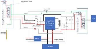
If I understand the response correctly, it looks something like this:

1669395382613.png
* In pass-through mode, the neutral is connected back to the grid neutral so the loads all 'see' the main bonding jumper.
* In inverter mode the Neutral is disconnected so there is no N-G bond.

In battery mode (or inverter mode), the output N-G will carry a voltage (float) due to inverter's full bridge design. In that case, you will probably want to do a N-G bond somewhere in the output distribution panel which I believe is the normal way to do this.
This could be done with a relay, but what signal are you supposed to use to drive the relay?

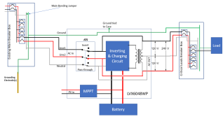
The only solution I see is to tie the input neutral and output neutral together external to the unit. This would ensure the output circuits will always 'see' the NG bond in the Main breaker box. It will probably work, but is it supported?
 
The only solution I see is to tie the input neutral and output neutral together external to the unit. This would ensure the output circuits will always 'see' the NG bond in the Main breaker box. It will probably work, but is it supported?
This is the only option that I recommend. (If the equipment doesn't do dynamic bonding)
My conscience won't allow me to recommend anything else.
As far as being supported by the manufacturer, I really don't care. Safety is my main concern.
Besides, if the unit is fine with it in bypass mode. I don't see why it would be a problem in battery mode.
The same output side of internal components is being used in both modes.
That is likely the main option I will be presenting to the inspector to see if they accept it outright or prefer a different method.

I'm hoping MPP does send me the wiring diagrams in case he has questions before responding.

Being CSA approved (inspected in batches in Canada from what I gathered from the distributor here, given only specific serial numbers get 'certified') will likely help.

Edit: *if* I decide to go with this unit
 
Last edited:
This could be done with a relay, but what signal are you supposed to use to drive the relay?

Update from MPP, not sure it changes anything since it still seems to eliminate the path back to the main panel while running off battery:


I wish to make a correction actually - the LVX6048WP is an exception to the "normal" N-G bond rule we have, and this particular model actually is N-G OPEN all the way, in any mode, so I don't think you have to worry about this now.
 
Last edited:
Back
Top