diy solar

diy solar

Growatt 48v 3000 Open Neutral

jkp

New Member
Joined
Aug 29, 2021
Messages
34
Testing a new Growatt 3000 using just an extension cord and noticed that if the inverter is holding the load via utility the output looks as expected but if running from battery there is an open neutral. Is this a normal and expected result?

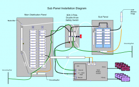
Here is my initial design. It has a primary main panel and a sub panel. The sub panel can be isolated to run either from the grid or from the inverter but it the inverter is providing different feeds to the sub panel (open neutral on battery and not on util) this will complicate things I would image.

comments?
1630335152465.png
 
Last edited:
Specifically is the open neutral coming from the inverter output expected?
 
Testing a new Growatt 3000 using just an extension cord and noticed that if the inverter is holding the load via utility the output looks as expected but if running from battery there is an open neutral. Is this a normal and expected result?

Here is my initial design. It has a primary main panel and a sub panel. The sub panel can be isolated to run either from the grid or from the inverter but it the inverter is providing different feeds to the sub panel (open neutral on battery and not on util) this will complicate things I would image.

comments?

View attachment 62146
Do you mean it is not shown Neutral is not bonded to Ground when you are in Inverter mode running from batteries?
Or you mean Open Neutral circuit?
 
I have 120v between Hot and Neutral, but also have ~58v between hot and ground and neutral and ground but this is only when running on battery. When running on utility mode (option 1, utl) the voltage is as expected.

Also was using one of those yellow tester plug that shows how the receptacle is wired.

As I am new to Inverters just double checking everything at every step. The issue that output On Battery is different than On Utility just seems odd.
OK, the word 'Open Neutral' in this case is not referring to 'Open Neutral circuit', it is about Neutral not bonded to Ground.
What is the exact model of the Growatt? Need to find out in the user manual to see if it has Neutral to Ground relay that will tie the Neutral to Ground when in the unit is inverter mode or not.
 
are you sure the output isn't 230 (220) volts ac. If it is, then you need to add an auto-transformer to get the natural and 120 volts to run your load. - In my case, to power the house.
 
BTW, are you bonding the Neutral and Ground at the sub panel? You should read this.
 
OK, the word 'Open Neutral' in this case is not referring to 'Open Neutral circuit', it is about Neutral not bonded to Ground.
What is the exact model of the Growatt? Need to find out in the user manual to see if it has Neutral to Ground relay that will tie the Neutral to Ground when in the unit is inverter mode or not.
It's a SPF 3000 TL LVM-48P.

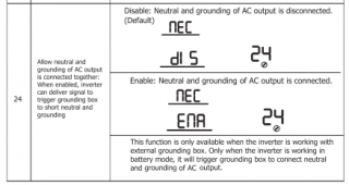
I saw that, it's option 24 I believe. I thought that option was for adding a external relay/contactor to open/close the bond at the external panel.
 
are you sure the output isn't 230 (220) volts ac. If it is, then you need to add an auto-transformer to get the natural and 120 volts to run your load. - In my case, to power the house.

Yes, its 120v, single phase.
 
BTW, are you bonding the Neutral and Ground at the sub panel? You should read this.

I have not added the sub panel yet, this was just a quick test to ensure that I could power something from the utility and from the battery. Having the different results is what is confusing me. Following my above diagram when the safety switch in the "inverter" position and if power is coming from the utility it looks to be bonded, but when its on battery it is not. If that is "normal" then I'll have to add in some additional components to handle dual possibilities for as I understand I cannot be bonded in multiple locations concurrently.

I'll review the link, it may clear things up.
 
I did not download the manual yet to see what it says about bonding Ground and Neutral.
 
Can you have all of the neutrals (or possibly the grounds) inner-connected in the safety switch? In my diagram I was switching both the ground and neutral independently.
 
1) I do not understand the drawing of the Safety switch, it shows 3 Busbars and described as 'Double Throw Switch', if it is double throw switch then the drawing should show what circuit is connected to what circuit when the switch is in certain position.
Since you are trying to switch 3 circuits (Line, Neutral, and Ground) as shown in your drawing then it is 3-Pole Double Throw switch (3PDT) so it should have C (Common terminals), N.O. (Normally Open terminals), and N.C. (Normally Close terminals).

2) Is the Main Distribution panel also connected to the Utility power from power pole for your house?

The drawing as shown right now you will have Load current flowing in the Ground wire and the Neutral wire which definitely a no no, the ground wire is for fault current only.

Right now based on you drawing, if 'the inverter is holding the load via utility the output' as you describe , if you put AC clamp-on meter on any of the ground wires, does it show any current reading?
 
Last edited:
1) I do not understand the drawing of the Safety switch, it shows 3 Busbars and described as 'Double Throw Switch', if it is double throw switch then the drawing should show what circuit is connected to what circuit when the switch is in certain position.
Since you are trying to switch 3 circuits (Line, Neutral, and Ground) as shown in your drawing then it is 3-Pole Double Throw switch (3PDT) so it should have C (Common terminals), N.O. (Normally Open terminals), and N.C. (Normally Close terminals).

2) Is the Main Distribution panel also connected to the Utility power from power pole for your house?

The drawing as shown right now you will have Load current flowing in the Ground wire and the Neutral wire which definitely a no no, the ground wire is for fault current only.

Right now based on you drawing, if 'the inverter is holding the load via utility the output' as you describe , if you put AC clamp-on meter on any of the ground wires, does it show any current reading?
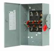
My picture is not as concise as it should be. Yes, its a 3 pole, double throw safety switch to move two power sources to a single load. Something like this.

1630294346990.png

Yes, the main panel is connected to the utility grid. My plan is to move off circuits from the main panel to the sub panel. Starting with the critical circuits.

I tried to clean up the drawing a bit. See if it now makes any more sense.

When I test each lead with a volt meter in the Battery mode all wires had some voltage. 118v Neutral to Hot, 65 Hot to Ground, 53 Neutral to Ground. In Util Mode, 125v Neutral to Hot, 125v Hot to Ground, 0v Neutral to ground.

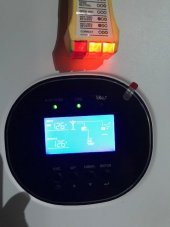
On Util, two lights is correct

IMG_2438.jpg

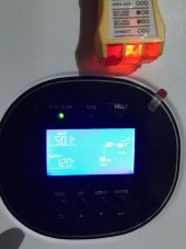
On Battery one light, Open Neutral.

IMG_2439.jpg
 
Tomorrow I'll enable option 24 and see if makes any difference.
 
What you should do is to have just an AC outlet (you can use cut power cord extension receptacle side) connected to the Growatt AC output, and no utility connected to the Growatt
Then you can play with setting to see if the Neutral to be Bonded to the Safety Ground or not, then we can go from there as how the Neutral and Ground be bonded together, but the bottom line it that it should only be done at only one point, I.E. the main source only (as you see on the link I provide), if you do it at more than one point then you will have load current flows in the safety ground wires which will be bad.

 
Last edited:
What you should do is to have just an AC outlet (you can use cut power cord extension receptacle side) connected to the Growatt AC output, and no utility connected to the Growatt
Then you can play with setting to see if the Neutral to be Bonded to the Safety Ground or not, then we can go from there as how the Neutral and Ground be bonded together, but the bottom line it that it should only be done at only one point, I.E. the main source only (as you see on the link I provide), if you do it at more than one point then you will have load current flows in the safety ground wires which will be bad.

Thank you, I'll read through these suggested links and also setup a new testing environment.
 
Bud, I think that I have it worked out. I'm waiting on my electrician to chime in on the proposed solution. I'll update once I get their input.
 
Bud, I think that I have it worked out. I'm waiting on my electrician to chime in on the proposed solution. I'll update once I get their input.
I think you need to leverage the dry contactor relay (3amp max) on the bottom connected to a larger relay handling the neutral bonding duties when running on battery. I‘ve upgraded my Growatt‘s firmware (same as yoursj but option 24 doesn’t exist.
 
Back
Top