diy solar

diy solar

Growatt and Circuit Breakers

Zero_PD

New Member
Joined
May 20, 2022
Messages
27
Location
SF Bay Area
Hi all,

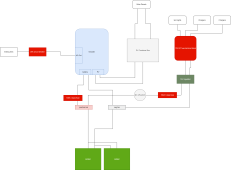
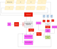
I'm working on the system diagram for my first off-grid system and I'm having a tough time answering a question about circuit breakers. I've read through the manual for the Jakiper 48V batteries and the Growatt SPF 3000 but I fear my electrical knowledge is a little rusty. The diagram is below - all breakers/fuses are in red. My main questions are about the Growatt.

  1. Should I have a circuit breaker in between the Growatt and my battery bank? The manual says "it’s requested to install a separate DC over-current protector or disconnect device between battery and inverter". Does 100A look right? And - pardon the rookie question - what is this protecting against? A short which would try to pull too much current from the Growatt?
  2. Should I have a circuit breaker between the Growatt and my AC Load? Since the growatt is 3000w at 120V I assume it can only source 25A, which is why I tossed a 25A circuit breaker in the diagram. Would love to know if I am off base here.

Thanks for your help!!


10kwh diagram.drawio (5).png
 
Should I have a circuit breaker in between the Growatt and my battery bank? The manual says "it’s requested to install a separate DC over-current protector or disconnect device between battery and inverter". Does 100A look right? And - pardon the rookie question - what is this protecting against? A short which would try to pull too much current from the Growatt?
100A seems about right.

The breaker/fuse is to protect from a short that would dump lots of energy from the battery. Consequently, the breaker or fuse should be as close to the battery as possible.

Note: If you decide to use a breaker, make sure it is DC rated and *not* a polarized breaker.

Should I have a circuit breaker between the Growatt and my AC Load? Since the growatt is 3000w at 120V I assume it can only source 25A, which is why I tossed a 25A circuit breaker in the diagram. Would love to know if I am off base here.
Good question.

I like to put in a breaker. If nothing more it makes a good disconnect. The question about the size of the breaker creates a bit of a dilemma.

Unless it is rated to run at full load, a breaker should be sized at 125% of it's normal full load. In this case 25A is the normal full load so the breaker should be 25A *1.25 = 31A. However, as you point out, the inverter is limited in its output so it may never be able to pop a 31A breaker.
 
Thanks so much!

100A seems about right.

The breaker/fuse is to protect from a short that would dump lots of energy from the battery. Consequently, the breaker or fuse should be as close to the battery as possible.

Note: If you decide to use a breaker, make sure it is DC rated and *not* a polarized breaker.

Follow up question: should this fuse between my battery and Growatt be a "T-Class" fuse?

I see on Will's website he links to 200 and 300A versions for a 48V system, but (unless I missed it) he doesn't write how he sizes them. I got 100A from the Growatt manual, and was planning to use a standard 100A circuit breaker.

breaker.jpg
 
Last edited:
Should this fuse between my battery and Growatt be a "T-Class" fuse?
Good Question..... Long answer,

That depends on the Amp Interrupt Capacity (AIC) of the breaker. When a short circuit happens the amps immediately jump really high before the breaker can pop. That means that when it does pop it has to disconnect a huge current and extinguish the resulting arc. The AIC rating tells you how much the breaker can safely disconnect. A class-T fuse has the fusible link encased in silicate sand that will snuff out the ark for up to 20,000 Amps. This seems like a lot, but LiFePO4 cells have a super low internal resistance and they will gladly dump huge currents while they destroy themselves and the arc in the breaker starts a fire.

Your next logical question should be: What AIC rating should I look for...... and there is no clear answer for that. Every bus-bar, BMS, shunt, wire, and connection in series with the fuse will add resistance and reduce the total possible short circuit current. The problem is that is really hard to get a good estimate of the total system resistance.

Let's assume there is only one battery and the total resistance between the battery and the short is 5mOhm (.005 Ohm) A 48V system with 5mOhm could generate 60V/.005R=12,000A. However, you will have two batteries in parallel so the total resistance will be cut nearly in half so 60/.003=20,000A. (I suspect the total resistance will be more than my assumption and the peak short circuit current will be less than 20KA, but it is difficult to prove. (Someday I might set up some experiments to come up with ballpark estimates for various types of components and connections.....but I have never seen something like that from anyone else)

I do not recognize the brand of the breaker you linked to so it might be a challenge to find it's AIC rating. Furthermore, many of that style breakers are made by questionable dealers and are known to not work well. The one you linked to might be fine, but I don't recognize the brand. I would stick with Bussman or Blue Sea brand for the breaker.....but even then I would only use the breaker if the AIC rating was in the 20KA+ (I suspect the breakers have an AIC rating of 10KA or less)

My philosophy on Fuse vs Breaker has changed over time. I used to insist everything be breakers, but the more I learned about high current breakers, the more I realized even the good ones were not as reliable as a properly specified fuse. I am now of the opinion that fuses are safer and are probably the best answer for the main system fuse. Furthermore, in a properly designed system, the main system fuse should only pop in a catastrophic (presumably unusual) situation. If it pops on a regular bases, there is something wrong with the system design.
 
he doesn't write how he sizes them.
Here is how I size them:

 
FilterGuy, thanks again for all your help. I read your document and it seems to confirm the manual's suggestion of 100A protection on the battery input. (3000/48/.9) x 1.25 = ~86, so they rounded up a bit more. It also confirms the 4awg wire I planned to use on that connection.

I also checked and even the BlueSea version of the 100A breaker only has 3000A interrupt capacity at 48V, so I see what you mean about it not being acceptable for these batteries.

One more question: I noticed in Will's "quick 48V system build" video, he does not use a fuse or breaker between the battery and the hybrid inverter/charger. He points to the circuit breakers built into his 48V server rack battery. If batteries - like my Jakipers - have a built in circuit breaker, do I still need this 100A fuse between my Jakiper and my Growatt?
 
Last edited:
FilterGuy, thanks again for all your help. I read your document and it seems to confirm the manual's suggestion of 100A protection on the battery input. (3000/48/.9) x 1.25 = ~86, so they rounded up a bit more. It also confirms the 4awg wire I planned to use on that connection.

One more question: I noticed in Will's "quick 48V system build" video, he does not use a fuse or breaker between the battery and the hybrid inverter/charger. He points to the circuit breakers built into his 48V server rack battery. If batteries - like my Jakipers - have a built in circuit breaker, do I still need this 100A fuse between my Jakiper and my Growatt?

With a single battery, it is probably fine to count on the built-in breaker (We have to assume they have specified the breaker correctly).
The BMS in the battery also has over-current protection so, between the two, you are probably OK. However, you need to size the wire to handle whatever current the breaker is for. (BTW: In a short circuit scenario, the BMS is likely to shut off first. That is a bit unfortunate because shutting off a really high current with a bunch of parallel FETs has the distinct possibility of damaging one or more of the FETs.)

When you start paralleling the batteries, things are different. In most cases, with a parallel battery, the combined current of all the battery breakers is considerably less than what is needed by the inverter, Consequently, the wiring can be smaller..... but that requires some type of current protection at the point all the parallel batteries come together.

I don't know what the breaker size is on the Jakiper, but for the sake of an example, let's say it is 100A. That means that in the circuit you show above, a problem right at the inverter could draw 200A before either of the breakers would pop. (Since breakers are slow blow, it could be a lot more than 200A for quite a while before they pop). That means the wiring from the point the batteries combine to the inverter would need to be sized for at least 200A.... but you only need 100A. Furthermore, once one of the breakers pops (Or BMS shuts down) all the load will shift to the remaining battery. The BMS on that battery will shut off and there is a distinct possibility the FETs will be damaged. (This is why you see limits for the number of parallel batteries in some battery specs). By putting 100A circuit protection device there, it will be more likely to pop than either the BMSs or the battery breakers.... and you can use smaller wires.

I personally would put a 100A Class-T fuse where you show the breaker. This allows for smaller wires and fuses the system for only what is needed.
(I do not like high currents if I can avoid them. Therefore, I like to design my safeties for the highest current values the system will ever need.... and no higher.)

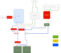
Amazing, I've updated my diagram with a 100A Class T fuse between the Growatt and the battery.

Another question: should I put the same thing between my DC bus bar and the battery? It seems that by the same logic, I should. If there is a short right at the 12V regulator, I want some protection for the wiring in between the regulator and the batteries.

Here is a diagram I've created of the physical layout of the polycarbonate or FRT plywood I'm going to mount my Growatt/Combiner Box/fuses/terminals to. I've placed 2 T class fuses on it - though that destroys my budget - t class fuses and holders are expensive!

(White boxes are non-physical load representations, the rest are physical units.)

physical star layout.drawio.png
 
Wait....I just realized if I move the T Class Fuse to closer to the battery (before the Positive bar), it will protect against a short at either the Growatt or the 12V bus/regulator ?‍♀️. I wouldn't know for sure which had failed, but it would be a lot cheaper!
 
A few points:

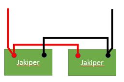
* It is hard to tell from the diagram, but it looks like both the positive and negative connection to the rest of the system will be made at the same battery. This will work OK, but one battery will be exercised harder than the other. I would recommend hooking the, up 'diaganal' to prevent this.

1653259315773.png

Wait....I just realized if I move the T Class Fuse to closer to the battery (before the Positive bar), it will protect against a short at either the Growatt or the 12V bus/regulator ?‍♀️. I wouldn't know for sure which had failed, but it would be a lot cheaper!
* Your post came through just as I was about to point that out. In addition, the fuse should be as close to the battery as possible. (Anything before the fuse is not protected from a short).

However, the size of the fuse and the size of the wire to the bus bar and inverter may need to be increased. What are the specs of the 12V converter?

* I am sure your 12v converter is a lot lower current and you will not be putting smaller wires to it. Consequently, you need to put a fuse on the positive wire going to the converter that is appropriate for the current draw of the converter. The type of fuse for this is a conundrum for me. After the main fuse, everyone uses lower-cost fuses after the main class-T fuse. Some people even use automotive fuses. These fuses don't have a very high AIC rating and rarely have a rating for 48V systems, but it seems to be working for people.

* speaking of the 12V converter; does it have low voltage disconnect? If not, it will be able to drain the battery till the BMS turns things off.
This is not the end of the world, but I like to have the loads shut off before the BMS does. (2 lines of defense).

BTW: You may want to review this:
 
Wow - your "Fuse and breaker sizing and placement" document is invaluable! I was missing a lot.

I redid a lot of things based on that.

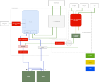
  1. Moved the Class T fuse before the positive bus bar. I sized it for 125A, based on 1.25x the maximum continuous discharge current of the Jakiper, which is 100A. Does this seem correct?
  2. I added an OCPD inbetween the Positive bus bar and the Inverter/Charger. Based on the Inverter Max PV charging current of 80A, I sized it for 100A (this is also what the Growatt manual recommends). I'm hoping for this I can get away with a more affordable Blue Sea System 100A circuit breaker, but I could still be missing something. I could also use the 100A ANL fuses.
  3. Added an OCPD between the positive bus bar and the DC load. Since the regulator is rated for 720W and 60A, I sized it for 80A. I am a little hazy on this. Does it seem right?

I also added in color coded wire gauges.

  • I sized Class T fuse wire (OCPD1) at 4awg. Since the fuse is 125A, I should probably step this up to 2AWG, but I've read it's hard to fit higher than 4 on the Jakiper, so I'm hoping 4 is adequate. I can reconsider if this seems like a critical mistake. I'm slightly violating Ampacity > Fuse > Current.
  • The line to the 12V regulator I also use 4AWG, since that can take me up to 100 and my regulator is at 60 (I do not believe it has low voltage protection).
  • From the combiner box to the Growatt, the current will vary from 20 to 30 amps depending on whether I do 2-3 strings (still TBD). I could step up to 8AWG but I think 10 will be sufficient. Most everything else is 10AWG as well.

Please let me know what you think and thank you again for all your help.


physical star layout.drawio (1).png
 
Is the dc converter 60A out? If so the input current will be *much* less. Nomally the 48V input current will be 1/4th the output current but with inefficiencies it will be a bit higher. Assuming 90% efficiency, my pass estimate is (60/4)/.9=16.7A The fuse for that should be 16.7A x 1.25 = 20.8A Either round that to 20A or 25A. for the fuse and the wire sizing.

Other than that, nothing jumps out at me.

From the combiner box to the Growatt, the current will vary from 20 to 30 amps depending on whether I do 2-3 strings (still TBD). I could step up to 8AWG but I think 10 will be sufficient. Most everything else is 10AWG as well.
You may want to review this:
 
Ok great. That's a good point on the oversized breaker for the 12V regulator. I've dropped the breaker size to 25A and I've dropped the wire gauge to 10AWG. But, since the output of the regulator can go up to 60A, I still need to switch to beefier wire for the regulator to the DC terminal block, correct?

One other question. I've gone down a rabbit hole about AC and DC circuit breakers. I was planning on using a Blue Sea system 25A circuit breaker on the Growatt AC output but I've realized that's a DC circuit breaker. What sort of OCPD do you like to use on your AC output?
physical star layout.drawio (2).png
 
But, since the output of the regulator can go up to 60A, I still need to switch to beefier wire for the regulator to the DC terminal block, correct?
Correct.
One other question. I've gone down a rabbit hole about AC and DC circuit breakers. I was planning on using a Blue Sea system 25A circuit breaker on the Growatt AC output but I've realized that's a DC circuit breaker. What sort of OCPD do you like to use on your AC output?
You have run headlong into a frustrating lack of AC breakers that don't require a breaker box. Last time I searched, I did not find breakers I liked and I I ended up with a small breaker box andtwo breakers.
 
Correct.

You have run headlong into a frustrating lack of AC breakers that don't require a breaker box. Last time I searched, I did not find breakers I liked and I I ended up with a small breaker box andtwo breakers.

Well, I'm glad I'm on the right track then haha! I added a cheapo from Amazon to my cart...I prefer name brand but have maxed out my BOM and can't spend another 150+ on a blue seas system marine breaker and breaker box. Fingers crossed this simple 32A AC breaker can do its one job.

Do you believe the DC power switch next to the 25A circuit breaker is redundant? Could I just use the circuit breaker as a switch?

Lastly, AC output question for you. I need to wire up the AC output. I've watched a number of Will's videos, and in a couple of them he wires up a basic power strip to AC out, with the disclaimer that because it's only rated for 15A/1800W to make sure you're not pulling more than that. Of course my Growatt can source 3000W/25A, so I want to be able to source that much without frying anything. I have one large 15A/120V pump, but should still have 10A left over. Problem is I can't find a beefy 30A power strip to simply buy and wire in. I've found some welding extension cords that are rated for 3kW, but then I would have only one single input, and I need to be able to plug my pump and a couple smaller appliances.

So right now I'm thinking I:
  • buy 8/3 cable
  • wire it up to the AC output
  • wire that up to 3 terminal bars
  • splice one 15A power strip and one plug to the terminial bars. Plug the pump into the plug, and make sure not to plug more than 10A into the power strip.
It seems a little convoluted though - I wonder if there's an easier way of breaking out the AC output to a couple power strips or plugs, or finding a heavy duty power strip that can support 3kW. Do you have any advice?
 
Last edited:
I added a cheapo from Amazon to my cart...I
That will probably do fine.
Do you believe the DC power switch next to the 25A circuit breaker is redundant? Could I just use the circuit breaker as a switch?
If you think you will be flipping the circuit on and off a lot, I would keep the switch. Circuit breakers are not really designed to be flipped on and off a lot.
Lastly, AC output question for you. I need to wire up the AC output. I've watched a number of Will's videos, and in a couple of them he wires up a basic power strip to AC out, with the disclaimer that because it's only rated for 15A/1800W to make sure you're not pulling more than that. Of course my Growatt can source 3000W/25A, so I want to be able to source that much without frying anything. I have one large 15A/120V pump, but should still have 10A left over. Problem is I can't find a beefy 30A power strip to simply buy and wire in. I've found some welding extension cords that are rated for 3kW, but then I would have only one single input, and I need to be able to plug my pump and a couple smaller appliances.

So right now I'm thinking I:
  • buy 8/3 cable
  • wire it up to the AC output
  • wire that up to 3 terminal bars
  • splice one 15A power strip and one plug to the terminial bars. Plug the pump into the plug, and make sure not to plug more than 10A into the power strip.
For 25A, you only need 10AWG.

Standard household receptacles are rated for 15A. Consequently, no one makes cords with a standard 2 or 3-prong US plug with 10AWG wire.

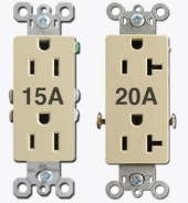
You may have seen some receptacles that have a slot that will take a horizontal prong as well as the vertical prong. These are 20A plugs. You can buy extension cords with the horizontal plug..... but since it is only 20A, no one makes the cords larger than 12AWG.

1653431839698.png

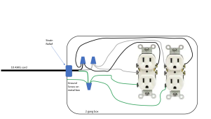
Sadly, that leaves you with building your own distribution. In your case, you would want a 10AWG cord that goes to two 15A receptacles.
Perhaps you could get a 2 gang box and string your 10AWG to that. Inside that, you would use wire nuts to split out each line into two 12AWG wires that go to each receptacle. (Make sure to use the right size wire nut.)


1653432430965.png
 
As always, thank you for your in depth response. This is the project that keeps on giving haha. Ok, making my own distro box it is. I watched a few youtube videos on how to wire up an outlet receptacle and seems straightforward enough.
  • The videos I watched just had me wiring neutral, line, and ground to the 20A receptacle or receptacles. Is the additional grounding to a metal gang box necessary? Some of the ones I'm looking at are plastic.
  • Just did another 20 minute deep dive on NPT strain relief cord grips hah. It looks like for 10/3 wire, according to the internet it has a 16mm OD and would require a 3/4 NPT cord grip, does this sound right to you? And for your receptacle enclosure, I would just drill a hole for this (another reason I'm looking at plastic enclosures)? That is a large drill bit. I'm guessing folks usually usually use circular hole-saw bits for this?
  • 10/3 25' cable is prohibitively expense, and 25' is the min size i've been able to find. Do you foresee any issue with me grabbing a cheaper 6 ft 10/3 extension cord and cutting the ends off and using that?

Goodness. I may have bitten off more than I can chew but no one can say I'm not learning!
 
The videos I watched just had me wiring neutral, line, and ground to the 20A receptacle or receptacles. Is the additional grounding to a metal gang box necessary? Some of the ones I'm looking at are plastic.
If you use a plastic box, the ground to the box is not necessary.

Just did another 20 minute deep dive on NPT strain relief cord grips hah. It looks like for 10/3 wire, according to the internet it has a 16mm OD and would require a 3/4 NPT cord grip, does this sound right to you? And for your receptacle enclosure, I would just drill a hole for this (another reason I'm looking at plastic enclosures)? That is a large drill bit. I'm guessing folks usually usually use circular hole-saw bits for this?
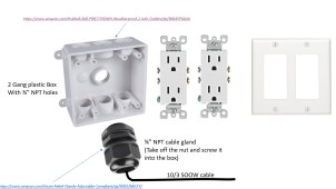
I was thinking something like this (No drilling).
1653451477647.png

Go to the nearest big-box Hardware store and see what they have. (There are other combinations than this). They may not have the cable gland but they will have everything else.

https://www.amazon.com/Strain-Relief-Glands-Adjustable-Compliant/dp/B092ZMJCFY/
https://www.amazon.com/Hubbell-Bell-PDB77550WH-Weatherproof-2-Inch-Outlets/dp/B0045PQ64U

10/3 25' cable is prohibitively expense, and 25' is the min size i've been able to find. Do you foresee any issue with me grabbing a cheaper 6 ft 10/3 extension cord and cutting the ends off and using that?
The hardware store will probably sell SOOW cable by the foot. If not a local electrical supply store would. Note: You can use SJOOW cord as well. (SOOW is 600V SJOOW is 300V).
 
That will probably do fine.

If you think you will be flipping the circuit on and off a lot, I would keep the switch. Circuit breakers are not really designed to be flipped on and off a lot.

For 25A, you only need 10AWG.

Standard household receptacles are rated for 15A. Consequently, no one makes cords with a standard 2 or 3-prong US plug with 10AWG wire.

You may have seen some receptacles that have a slot that will take a horizontal prong as well as the vertical prong. These are 20A plugs. You can buy extension cords with the horizontal plug..... but since it is only 20A, no one makes the cords larger than 12AWG.

View attachment 95705

Sadly, that leaves you with building your own distribution. In your case, you would want a 10AWG cord that goes to two 15A receptacles.
Perhaps you could get a 2 gang box and string your 10AWG to that. Inside that, you would use wire nuts to split out each line into two 12AWG wires that go to each receptacle. (Make sure to use the right size wire nut.)


View attachment 95706
Does there need to be a breaker(s) to prevent the outlets from pulling more than 15 amps (to protect the plugged in wiring from overheating if over-drawing), since 25 amps are potentially available? If so, then there needs to be two breakers so you aren't limiting useful output to only 15 amps then, right?
 
Does there need to be a breaker(s) to prevent the outlets from pulling more than 15 amps (to protect the plugged in wiring from overheating if over-drawing), since 25 amps are potentially available? If so, then there needs to be two breakers so you aren't limiting useful output to only 15 amps then, right?
I am not sure, but you are probably right. If it is a concern, make one of the recepticals a GFCI with the built in breaker.
 
Back
Top