Good morning ( at least on my side of the globe).
So I have successfully managed to "alter" the protocol between the Growatt ARK2.5L and the inverter and use DIY battery with the Growatt one - more details bellow - this will be big one.
1. I sourced locally 16s 280AHs LiFePo4 cells. I bought them 10 days ago with a BMS, produced by the same factory supplying the cells. The BMS is nothing fancy - 150A discharge, with simple Bluetooth app(can switch On/Off the charging and discharging, monitor SoC, cells Voltages) and RS485 out.
2. I build the battery and then attach it to the existing system by doing following steps :
- Disconnect only positive lead from the ARK2.5, but left all the rest connection in place (CAN bus, Neg.Lead)
- Connect DIY battery positive lead to the DC bus - the inverters starts charging it, but with the restriction mandated by the ARK (25A total charge current, 56.8 V max voltage).
- From time to time, I measured the voltage difference b/w the ARK and DIY battery. It took few hours of charging with ~1350W to reach 0.1 V difference b/w both batteries. Then I connected the positive lead of the ARK. Due to the difference of internal resistance majority of the charging current is going to the DIY battery, where the ARK took only few AMPs.
- I continue to monitor and control the system based on the SoC of the Growatt battery, but the DIY battery app was constantly showing 100%SoC, due to it was programmed, when cells reach 3.47V to cut and then start monitoring.
- After few days of work like that, the SoC of the DIY battery start to show values with 0.5-0.8% lower than what the ARK reported and difference b/w cells around 14-16mV( which I think is OK). I think when it reached those 3.47V per cell the it thinks that its top balanced and start to count from there, but due to the low charge current it took few days to go up to this voltages.
- Yesterday I disconnected the ARK and just for test switch the inverters to US2 battery - to test charging the DIY battery with big current and little bit higher voltage - 60A was ok, but it had hard time balancing 2 of the cells. The difference b/w the highest and lowest cell voltage gone to 170mV. At the end of the day I connected back the ARK and switch on to LI setting - after some load the DIY battery cell voltages set back to ~ 20mV.
During those 10 days I managed to get 4000+W of power out of both batteries without any cut in the supply due overload of the ARK. The only downside was that the charge current was set to 25A(1300W) and max charge voltage to 56.8V by the ARK, but it actually never goes to 55.4(this is another one that I want to change with at least 0.1V higher - keep reading ).
So to overcome this issues and satisfy my passion for microcontrollers and embodied devices - I cannot left the situation like that!

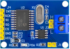
The idea was to sniff the CAN and see if I can alter the communication b/w the ARK and the inverted. So I bought single MCP2515 board with SPI interface and using one Arduino I was able to sniff how the ARK/Inverter is talking. Software for PC and Arduino is available here
https://github.com/adamtheone/canDrive - great tool runny on Python!
After logging 1000+ packets, trying different configurations(only battery connected, only inverter connected, change of reported SoC, battery in fault mode) I managed to find few candidates for what I need.
- Communication is 500kbits/s, SDT frame(no ext id), always broadcasted 8 data bytes.
- Invertor always broadcast id 0x301 data 0x0B,16,21,2C,37,42,4D,58 with static content - never changed.
- after connecting battery, one of the first IDs sent from the battery is 0x311 that by looking similar protocols(pylos battery I think) try to find it contains what I was looking for....and sure there was
, not the same as pylons batteries bot it was good guide line.
-knowing the battery limits i try to find them in ID 0x311 broadcasted from the battery - so bytes
--D0:D1 - contains the max voltage in unsigned int format for example 0238 = 568*0.1V = 56.8V max voltage limit
--D2:D3 - contains the max charge limit, unsigned int for example 00FA = 250*0.1A = 25A max charge current
--D4:D5 - similar to charge current
--D6:D7 - I guess some status bits
- SoC is recorded in ID=0x313, D6
So now knowing this I used the canDrive to sniff normal comunication for 1 min, then export this to .csv file and change all 0x311 IDs bytes D2:D3 to 0x1F4 = 500*0.1A = 50A. Disconnect the battery, load the changed log file and start broadcasting - and voala ! After 30 sec the parameter for max charge current was changed from 12A to 25A ( I have 2 iverter in paralel so total is 50A )
! Success - I took a beer?
When the battery is fully chaged the D2:D5 bytes are 0x00 - strange, but keep reading.
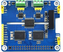
Next step - how to make it work - as you may know just broadcasting the revised 0x311 data on the CAN wont work, cause the battery will keep broadcasting its parameters - so I need a CAN gateway, sitting between the BMS and the inverter. I thought that Arduino Uno may be with insufficient processing power and since I have already DIY Battery with Bluetooth BMS, why note use NodeMCU32-S - it has quite fast MCU, Bluetooth and Wifi( to report later to my local python server already running - but this is another topic). I was thinking for Raspberry Pi, but its hard to find, expensive and required some kind of services running(may drop down). For the CAN hardware side I found MCP2515 dual CAN hat for Raspberry pi - perfect !
So I took one of my NodeMCU32s and using this library :
https://github.com/coryjfowler/MCP_CAN_lib, by tweaking a little bit the dual_can example I was able to make a CAN gateway working. On CAN1 attached battery on CAN0 attached inverter BMS port. Make a routine that forward evertithing form CAN1 to CAN0 except ID 0x311. For ID 0x311 I hard coded it into the MCU like that "byte id311[] = {0x02,0x39,0x01,0xF4,0x01,0xF4,0x00,0x61};" - for 50A charging current and 56.9(+0.1V) charging voltage. When I connected it it works
...the Inverted clicks and power the battery, inverter parameter 02 is 25A(50A for both inverters) and parameters 19,20 for charging voltages ware 56.9V...
What next - I want to change only D0:D5 parameters in 0x311 so the status bits are forwarded correctly to the inverter and test the setup for a few days(weeks) prior release of the code(most probably will make a github page). May be when everything is completed will raise another topic in this forum with all the steps and software, wiring diagrams - so it can be done by other persons. Will try to add Bluetooth support in this MCU- why not later adding Daly or other BMSs to this project and be like cross platform to Growatt inverter? Currently I am reverse engineering my BMS to take the SOC, current, Voltages (it uses Bluetooth LE UART) and once this is done, most probably will add and Wifi client ( HTTP ) so I can get the info from my DIY server running in my network(pulling info from growatt site) and providing the complete information there.
This is for now - will keep posting and for any questions I am available on private message or here in this topic.
PS quite long but I guess will be helpful if someone decide to do something similar.