diy solar

diy solar

Growatt DVM-MPV: How to verify/confirm Battery Charger is working?

Old_Skewler

Solar Enthusiast
Joined
Jul 30, 2021
Messages
510
Location
NYS
Very exciting, I believe I am making (slow) progress with my installation. I have been able to connect Generator to Inverter + Inverter to AC Subpanel. Yeah!!Everything is working so far: the inverter is reading the 240V from generator correctly and I am getting the correct 240V out in the subpanel.

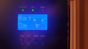
Before I continue to the next step, I need to confirm/verify that the inverter is charging the battery when generator is running and I can't tell from the display whether the battery charger is working.

Could someone with the same GroWatt DVM-MPV AIO inverter clarify how to read the display and verify if the battery charger is working correctly?

My Off-grid setup is the following:
- (1) 12kW Split Phase Generator located outside in a shed
- (1) 8kW Growatt AOI Split Phase inverter coupled to (1) EG4 100Ah Battery located in the same shed as generator
- (1) 100A Split-Phase panel inside the cabin with most loads wired 120V

I have made a video scrolling thru the Inverter display but I don't know how to add a video to the forum.
 
It does not appear to be charging. Can you tell me your settings; 1, 2, 5, 8, 9, 11, 12, 13, 19, 20, and 21? Hopefully it's something simple.

@BenFromSignatureSolar

Here are my settings:

My setup is the following:
  • Off-Grid
  • No Solar
  • Growatt 8kW DVM-MPV
  • EG4 48V 100AH


Current GroWatt Settings:
01 – SBU
02 – 50A
03 – APL
05 – US2
06 – LTD
08 – 240V
09 – 60Hz
11 – 50A
12 – 48V
13 – 56V
14 – CSO >> I also tried SNU but no success
15 – BON
16 – LON
17 – AON
19 – 58.0V
20 – 56.4V
21 – 44V


I am currently NOT able to connect the inverter to the BMS so I am using US2. I will fight this fight after I am able to properly set up the unit and charge the batteries.

Thank you,
 
Reason: you can't charge from utility, while connected to batteries.
 
Change settings
1. Utility first
14. SNU

Holy shit, it actually worked!! Power flicked for a second than the display changed to what I believe is the Utility Charging mode. Here is the photo:

20220719_215705.jpgThank you very much!
Do you happen to also know about the following:

- How to connect the generator to the GroWatt AGS? I know my generator has a dry contact with a regular switch on the wall. How do I wire this to the GroWatt dry-contact?

- What to do to be able to connect the Growatt to the Inverter BMS? I purchased a Cat6 cable off Lowes, if that matters
 
  • Like
Reactions: Rho
Reason: you can't charge from utility, while connected to batteries.

Huh?

I don't understand what you mean. I just changed the settings per your recommendation above and I am now charging the batteries from the utility (generator).
 
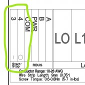
My generator has connections 3 & 4 for AGS which currently goes to a simply wall switch - I must leave generator in AUTO mode for it to work.

generator.jpg


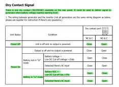
The Inverter has (3) dry contact ports, I just need help understanding how to translate the following table:

inverter.jpg
 
Huh?

I don't understand what you mean. I just changed the settings per your recommendation above and I am now charging the batteries from the utility (generator).
The reason it wasn't charging in SBU mode. Was because it was connected to the batteries, as a power source.
 
I believe you should connect the two wires to NO & C.

I will try that and test it, by temporarily changing the battery low-voltage AGS setting.

One thing just comes to mind though: is there a way to wire the AGS so that I still have the option to force RUN with the existing wall switch inside the cabin? In other words, is there a way to wire this so that either the inverter or the wall switch can turn on the generator?
Yes connect in parallel with each other.
 
The regular EG4, no display, only shows the SOC, which currently sits at full bars, so I believe 80%-100% SOC.
All 4 dip switches down, on the battery.
Connect the CAT6 cable to either port on the battery.
Not sure which port on your inverter. (Try both)
Set inverter to LI battery type, and give it a couple of minutes to communicate.
 
If you had to change the dip switches, you must restart the battery. (Turn the breaker off and back on)
 
Yes connect in parallel with each other.

I need to ask because it is not that clear to me how "connecting in parallel" would look like in this situation.

I have (3) sets of (2) wires total. (1) set from the generator board + (1) set from the inverter NO/C + (1) set from the wall switch.

Would connecting in parallel simply mean randomly picking (3) wires and connecting them and doing the same for the other (3) remaining wires?

I could be totally off on this one... I am very curious to understand how to wire this in parallel.
 
Let's call the wire sets , wire 1 and 2.
All 1's together. And all 2's together. (Which one is 1 or 2 does not matter)
 
Back
Top