


timselectric
If I can do it, you can do it.
- Joined
- Feb 5, 2022
- Messages
- 18,443
First, let's point out the issues with this inverter for use in a split-phase system.
1) this inverter was designed for use in a 230v grounded installation. (European standards)
It's input and output are L1 and "N". This input "neutral" is expected to be grounded by the grid, and at the building service main panel. In bypass mode, this grounded "neutral" is passed through the inverter to the loads panel. In battery mode, the inputs are disconnected and the inverter will internally bond the output "neutral" with the inverter case and ground terminals. (This connects a hot wire to ground, in the US)
When using this inverter in a split-phase configuration. You need 240v single phase ungrounded. Then you use a transformer to create the midpoint tap for the neutral.
This gives you 120/240 split-phase.
This neutral should be grounded at all times, for life safety.
Signature Solar has worked with Growatt to modify the design so that the 2 lines are ungrounded through the inverter. (By removing the grounding system on the main board.) This stops the internal grounding relay from connecting "N" to ground.
2) the use of an AT (auto transformer) , creates the neutral in a very efficient way. And does so in a small package.
It's connected to the loads panel and needs to have its neutral bonded to the ground.
But, if you bond its neutral at the loads panel, you will create a ground loop between the loads panel and the main panel. This happens only when the inverter is in bypass mode. This is undesirable and very dangerous.
To avoid the N/G loop. Run a neutral from the main panel to the loads panel. This neutral is already bonded at the main panel, and provides short protection at the loads panel.
But, this puts the AT in parallel with the grids transformer.
This is undesirable, because the AT can try to carry the loads of the grids transformer.
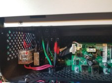
To solve all of these issues, this is what I have done.
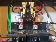
1) I ran a neutral conductor from the main panel to the loads panel. (Not bonded at the loads panel)
This provides a neutral for the loads in bypass mode. And provides the N/G bond from the main panel, in all modes.
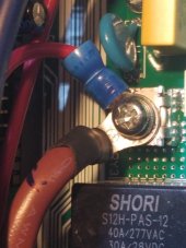
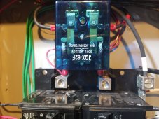
2) install a relay on the AT feed conductors. Which is controlled by the inverter grounding relay. To only turn on the AT in battery mode.
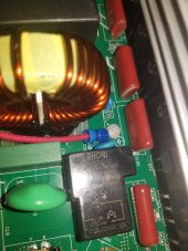
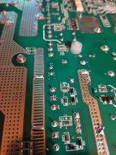
To access the inverter grounding relay signal, I connected to the board at the screw location that was designed to ground the output "N" in battery mode.
This was done by a ring terminal and a non conductive nylon 3mm x 8mm machine screw.
And another ring terminal at the internal "L" terminal. This gives me a 240v signal.
Now, the AT is never connected to the loads at the same time as the grid. (No load sharing)
And, the loads panel neutral is always bonded. (From the main panel's N/G bonding point)
I also added another relay between the inverter grounding relay signal and the AT relay.
This keeps the internal inverter power isolated from external power. (This was for my own piece of mind)
1) this inverter was designed for use in a 230v grounded installation. (European standards)
It's input and output are L1 and "N". This input "neutral" is expected to be grounded by the grid, and at the building service main panel. In bypass mode, this grounded "neutral" is passed through the inverter to the loads panel. In battery mode, the inputs are disconnected and the inverter will internally bond the output "neutral" with the inverter case and ground terminals. (This connects a hot wire to ground, in the US)
When using this inverter in a split-phase configuration. You need 240v single phase ungrounded. Then you use a transformer to create the midpoint tap for the neutral.
This gives you 120/240 split-phase.
This neutral should be grounded at all times, for life safety.
Signature Solar has worked with Growatt to modify the design so that the 2 lines are ungrounded through the inverter. (By removing the grounding system on the main board.) This stops the internal grounding relay from connecting "N" to ground.
2) the use of an AT (auto transformer) , creates the neutral in a very efficient way. And does so in a small package.
It's connected to the loads panel and needs to have its neutral bonded to the ground.
But, if you bond its neutral at the loads panel, you will create a ground loop between the loads panel and the main panel. This happens only when the inverter is in bypass mode. This is undesirable and very dangerous.
To avoid the N/G loop. Run a neutral from the main panel to the loads panel. This neutral is already bonded at the main panel, and provides short protection at the loads panel.
But, this puts the AT in parallel with the grids transformer.
This is undesirable, because the AT can try to carry the loads of the grids transformer.
To solve all of these issues, this is what I have done.
1) I ran a neutral conductor from the main panel to the loads panel. (Not bonded at the loads panel)
This provides a neutral for the loads in bypass mode. And provides the N/G bond from the main panel, in all modes.
2) install a relay on the AT feed conductors. Which is controlled by the inverter grounding relay. To only turn on the AT in battery mode.
To access the inverter grounding relay signal, I connected to the board at the screw location that was designed to ground the output "N" in battery mode.
This was done by a ring terminal and a non conductive nylon 3mm x 8mm machine screw.
And another ring terminal at the internal "L" terminal. This gives me a 240v signal.
Now, the AT is never connected to the loads at the same time as the grid. (No load sharing)
And, the loads panel neutral is always bonded. (From the main panel's N/G bonding point)
I also added another relay between the inverter grounding relay signal and the AT relay.
This keeps the internal inverter power isolated from external power. (This was for my own piece of mind)
Attachments

Last edited:
")