diy solar

diy solar

Growatt SPF-5000-ES AT and N/G solutions

In reverse, When the inverters internal N/G relay is open, then the N/C cube relay stays closed, which allows power from the load panel to go thru the cube relay and to the AT relay, which opens the N/C AT relay, stopping the AT from working?
So the power from the load panel to the cube relay (which is the signal for the AT relay to open) is supplied by the grid or the growatt depending on which one is powering the load panel?
 
In reverse, When the inverters internal N/G relay is open, then the N/C cube relay stays closed, which allows power from the load panel to go thru the cube relay and to the AT relay, which opens the N/C AT relay, stopping the AT from working?
Correct

So the power from the load panel to the cube relay (which is the signal for the AT relay) is supplied by the grid or the growatt
Also correct
 
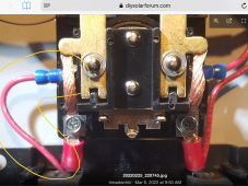
What is the purpose of the wire circled in yellow? Why is it connected to theload panels main lug.

EDIT, I suppose only the wire on the right is going to the cube relay. The wire I circled does not have to go to the cube relay. The right wire being severed from the cube relay opening is all that’s needed to allow the AT relay to close
 

Attachments

  • 7482A49A-33BB-4F6A-8B54-9AF5113B3FC9.png
    7482A49A-33BB-4F6A-8B54-9AF5113B3FC9.png
    1.6 MB · Views: 32
Last edited:
What is the purpose of the wire circled in yellow? Why is it connected to theload panels main lug.

EDIT, I suppose only the wire on the right is going to the cube relay. The wire I circled does not have to go to the cube relay. The right wire being severed from the cube relay opening is all that’s needed to allow the AT relay to close
Yup
You answered your own question.
 
In regards to the other posts, I thought the newest growatt 5000 inverters sig sells are the us model with the screw never installed not the other way around
 
Yep it is the correct screw. The same one everyone it pointing to in the pictures.

I was using a analog tester which I thought would read the potential between L1 or L2 to Gnd which usually will read like 170v or 70v or something like that (a split voltage) but i suppose it being an inverter the circuits will even them out. I don't have much experience working inside Inverters. Its always good to learn new things!.:)
Sadly, if this is how the ones from Signature Solar are going to be from now on. I will have to buy future additional models from somewhere else. At least the first one for each system. I don't see any other way to make it work correctly and safely.
 
In regards to the other posts, I thought the newest growatt 5000 inverters sig sells are the us model with the screw never installed not the other way around
Removed or never installed.
Same thing to me. As long as it is done at the factory, the warranty is still intact.
 
In regards to the other posts, I thought the newest growatt 5000 inverters sig sells are the us model with the screw never installed not the other way around
There is a lot of confusion going around about this from a single post by a Signature Solar employee making an in accurate statement.

Signature solar has been selling these for over a year now (I have two of the early one on my wall right now running by house). They were apparently shipped simply with the screw removed. (I have not opened mine yet to see). The newest ones actually have the screw intact and are un-bonded in a different way. (That is the part I am going to see if I can figure out)

Both modification were done by Growatt not Signature solar. This leads some to believe Growatt thinks there might be a problem with just removing the screw. However, if all they did instead was a Firmware update that doesn't active the bonding relay, (as I suspect they did) that would be even easier (cheaper) for them to do then removing a screw.

Really hoping there is something I can do to make it work so I can use it in the same way as this Post does!
It appears that the way to do it correctly and safely. Is to buy the European version for the first one, and set it up as I have. And then the US version as sold, for paralleling multiple units with the first one. This way, you still have a warranty on the US models, and a US distributor to handle warranty issues.
 
There is a lot of confusion going around about this from a single post by a Signature Solar employee making an in accurate statement.

Signature solar has been selling these for over a year now (I have two of the early one on my wall right now running by house). They were apparently shipped simply with the screw removed. (I have not opened mine yet to see). The newest ones actually have the screw intact and are un-bonded in a different way. (That is the part I am going to see if I can figure out)

Both modification were done by Growatt not Signature solar. This leads some to believe Growatt thinks there might be a problem with just removing the screw. However, if all they did instead was a Firmware update that doesn't active the bonding relay, (as I suspect they did) that would be even easier (cheaper) for them to do then removing a screw.

Really hoping there is something I can do to make it work so I can use it in the same way as this Post does!
It was a YouTube video from sig (not a post) where their engineer said that the growatt units they sell are different because the screw was never installed at all from the growatt factory. These are the units they call the US version.. I’ll share the video once I find it.
So if they did deactivate the bonding relay then with the grid with N/G bond attached to the inverter, how do we make sure there’s a N/G bond when the inverter is inverting from the battery.
The solution I posted is still valid, for that issue.
It's the auto transformer issue solution that may not work for the new Signature Solar models.
 
"Good news everyone!" haha --The relay is still active. The bad news it is no longer tied to the ground screw in the newer "US" models.
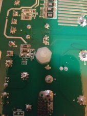
This will mean I have to take the whole unit apart to get access to the back side of the main board. There I will most likely have to solder a wire to relay directly. (not an easy DIY project - I could not recommend it to the inexperienced - Your more likely to ruin your inverter then fix the problem)

I do plan on looking into this as I Voided my warranty already and I also agree with Tim that the neutral wire should run from Main Panel to the Sub Panel and be bonded only at the Main Panel (or Service Disconnect whichever you have) as it solves all grounding/ground fault issues. (This is not what Signature Solar recommends however)

As long as no one objects? - I will continue to update my progress in this thread as this was timselectric discovery. (about the relay acting as a Grid-vs-Battery signal) Full disassembly could take awhile...
Disassembly is actually pretty simple. I had an empty case in less than 5 minutes. There's very few jumpers between the boards. And I didn't see any duplicate ends. So, it went back together easily too.
Good luck and let us know how everything goes.
 
"Good news everyone!" haha --The relay is still active. The bad news it is no longer tied to the ground screw in the newer "US" models.
This will mean I have to take the whole unit apart to get access to the back side of the main board. There I will most likely have to solder a wire to relay directly. (not an easy DIY project - I could not recommend it to the inexperienced - Your more likely to ruin your inverter then fix the problem)

I do plan on looking into this as I Voided my warranty already and I also agree with Tim that the neutral wire should run from Main Panel to the Sub Panel and be bonded only at the Main Panel (or Service Disconnect whichever you have) as it solves all grounding/ground fault issues. (This is not what Signature Solar recommends however)

As long as no one objects? - I will continue to update my progress in this thread as this was timselectric discovery. (about the relay acting as a Grid-vs-Battery signal) Full disassembly could take awhile...
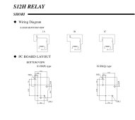
Done a little research on the N/G relay inside the inverter. It looks like pin #3 is where you need to solder to. (Please verify this)
 

Attachments

  • 20220307_080425.jpg
    20220307_080425.jpg
    106.2 KB · Views: 40
  • 20220222_084600.jpg
    20220222_084600.jpg
    110.3 KB · Views: 39
That is what I suspected. The newest ones from Signature Solar actually have the screw present. (I own one of the new ones...)
Now I will have to decide if its worth voiding the warranty to see if there is any ground signal present or it they simply removed the relay.
As it was Growatt itself that modified these units I have suspicion that the relay was simply removed.
Thanks for post!
Ours have a modification to the PCB board itself - it's of a different design to prevent the N/G issue completely.
 
Ours have a modification to the PCB board itself - it's of a different design to prevent the N/G issue completely.
I wish that they would put back in the setting for the provided dry contacts, that would allow us to control an external N/G relay. Otherwise, we are stuck with voiding the warranty to solder a wire to the back of the main board.

Edit: or buying the non modified version, elsewhere.
Which doesn't have to be completely disassembled, to access the switching signal.
I hear you. There’s a lot happening with everything in this capacity.
 
Back
Top