• Have you tried out dark mode?! Scroll to the bottom of any page to find a sun or moon icon to turn dark mode on or off!

diy solar

diy solar

Hacking the new Growatt WiFi-F modules

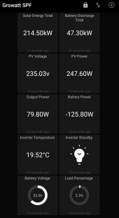
I've added some extra functionality that provides an option to use MQTT to remotely switch the inverter's AC output in and out of standby mode. This is a function not available through the inverter's interface and can save quite a lot of energy by reducing idle power consumption when the AC output isn't needed.
Battery charging still occurs while the inverter is in standby, which is nice.

All of this can be brought together in an app like MQTT Dash to provide real-time monitoring and a shortcut for the standby command.

Screenshot_MQTT Dash.png
 
Hi, do you think it is possible to get more information of connected batteries via the modbus?
 
Battery voltage and SOC are the only metrics available. You'd need to query your BMS if you wanted more detailed information.
 
Bonjour,

mon dongle wifi-f shine ne fonctionne pas. 3 leds allumées, pas de clignotement.
Jehink j'ai fait une erreur en essayant de mettre à jour le firmware de spf5000es.

Même si j'appuie longuement ou brièvement sur le bouton, aucun effet.
quelqu'un peut-il me dire comment mettre à jour le firmware ?
Je ne suis pas un super homme électronique, alors... processus simple s'il vous plaît.
nb : j'ai un ordinateur

Merci beaucoup
 
There's no special process that's specific to these modules, you can just follow the standard steps for flashing an ESP8266:
  1. Disconnect all power to the module.
  2. Short the GPIO-0 pin to ground.
  3. Apply power to the module. It will now start in serial bootloader mode.
  4. Connect your USB to UART adaptor to the GND, TX and RX pins.
  5. Upload the new firmware from your PC.
 
Il n'y a pas de processus spécial spécifique à ces modules, vous pouvez simplement suivre les étapes standard pour flasher un ESP8266 :
  1. Débranchez toute alimentation du module.
  2. Court-circuitez la broche GPIO-0 à la masse.
  3. Mettez le module sous tension. Il va maintenant démarrer en mode chargeur de démarrage série.
  4. Connectez votre adaptateur USB vers UART aux broches GND, TX et RX.
  5. Téléchargez le nouveau firmware depuis votre PC.
merci beaucoup.
ce pourrait vous m'envoyer le firmware officiel de growatt s'il vous plait ?
thanks a lot.
 
merci beaucoup.
ce pourrait vous m'envoyer le firmware officiel de growatt s'il vous plait ?
thanks a lot.
 
Spectacular thread, gentlemen. But I understand nothing of your magic :unsure:

Is this about obtaining activity reports of real-time and daily/history performance of a Growatt inverter ?
If you can pardon my ignorance; need to ask your expertise if it is possible to read real-time performance of a grid-tied Growatt MIN 6000 TL-X
with a smart phone (that has the WiFi feature) without any wireless router at all, no internet service at the premises, and without any participation of the Growatt server. My inverter <----> my phone in-range via WiFi. Or; removing the antenna and connecting a laptop via its USB jack.

I was suggested to use my phone as a 'hot spot' mode but that would still be to engage the Growatt server. I think.

If this is not pertinent to the thread, please delete or/and let me know to start a proper new thread with the subject. Thank you.
 
Here's my esp32 configuration which should help people with registers. This also lets you set settings from esphome or home assistant.

I've left out my specific stuff at the top. I just bought some esp8266s online and desoldered the esp-s and soldered the new one inafter flashing using a flasher.
 

Attachments

I am still having issues even getting my dongle to communicate with the Arduino IDE. It compiles no issue says its uploading but fails.
Im using a Cisco USB Console cable with the pins broken out to an rj45 socket I ahve then jumpered to my board.

I run OSX so dont see many applications to use for a serial test to see if it is at least communicating correctly or even getting to bootloader sequence. I have both a blue led and a red led visible so i suspect my module is fried.
 
Get yourself one of these:

Wishiot ESP8266 Burning Fixture Development Board Micro USB Port Onboard CP2102 Chip Support ESP-01S ESP-07 ESP-07S ESP-12E ESP-12F ESP-12S Easy Programer https://a.co/d/h989hLV

No guessing for boards that aren’t soldered in.

For ones soldered in download and 3d print one of the jigs on thingyverse.

But a soldered in board on the shine boards is basically useless because the Rx/tx are taken over by the external chip so you’re removing something one way or another. Easier to just remove and replace the esp chip.
that did the job nicely!
 
Firstly, thanks for the development and this thread - exactly what I needed.

I would appreciate it if someone can provide a bit of assistance. I managed to flash the dongle, however, following the flash, the dongle has the green and red LEDs as solid with the blue led periodically flashing shortly. On my router it connected momentarily but then drops and stays disconnected. Any idea what this means?


------------------UPDATE-------------------------
It seems like it needs to be connected to the Inverter to enable it to connect to Wifi...
 

Attachments

Last edited:
Firstly, thanks for the development and this thread - exactly what I needed.

I would appreciate it if someone can provide a bit of assistance. I managed to flash the dongle, however, following the flash, the dongle has the green and red LEDs as solid with the blue led periodically flashing shortly. On my router it connected momentarily but then drops and stays disconnected. Any idea what this means?


------------------UPDATE-------------------------
It seems like it needs to be connected to the Inverter to enable it to connect to Wifi...

i didn't have to have mine connected to the inverted. i did however have to power it via the usb a connection.
my computer would not see the ssid of the dongle but my phone did. as soon as it connected to my phone my primary network for local wifi were transferred over and it started working on my local wifi.
 
Hi

Did anyone get something like this working using the RJ45 - RS485 port. I would like to try using modbus with that port and keep the ShineWifi connected for now. I cant manage to get the inverter to send any info via the port. And when i do get info it is full of CRC errors
 
Hi all, just sharing my recent experience working with a Growatt SPF 3500 ES and the included WiFi-F module. I have a few other solar systems already feeding their data into InfluxDB and Grafana, and wanted the new Growatt unit to do the same.

Otti’s project on GitHub provided some inspiration, however the newer generation Wifi-F module proved to be a challenge to interface with. I spent quite a while trying to communicate with the ESP8266 using a few different serial adaptors (Silicon Labs, FTDI and CH340), however all attempts were failing very quickly with various serial communication errors.

In the end I found that the SIPEX SP3232EE RS-232 transceiver on the rear of the PCB, which is also connected to the RX and TX pins of the ESP8266 was the culprit. As a workaround I tried interfacing with the SIPEX chip’s own RX and TX pins, however this didn’t work. The only solution I could find was to remove the chip from the board temporarily while I uploaded new firmware.

Once the SP3232 chip is removed, the ESP8266 is easy to work with. All the necessary pins (GND, TX, RX and GPIO-0) are broken out to a standard 0.1” through holes that a pin header can be soldered to. The chip can be placed in flash mode by shorting GPIO-0 to ground while it's reset.

I included OTA components in my firmware so any future updates could be done without a serial interface, then re-soldered the chip. From here everything worked perfectly.

Another note is that the board seems to be quite power hungry, I had it running from a good quality USB power bank, however it would reset itself during firmware updates. Powering it from a higher voltage source solved this issue. It has an onboard buck converter, so it's happy to accept well over 5v.

The end result was the Growatt reporting all its statistics into InfluxDB and Grafana, screenshots are attached. I’d be happy to upload my code to Github if anyone is interested.
I’ve also attached photos of the WiFi-F unit and each side of its PCB.


Edit 30/09/2022:
Code and updated instructions posted to GitHub. It's possible to upload the new firmware without cutting traces or removing the SP3232 chip by using a Silicon Labs CP2102 USB to UART adaptor. These are unique in that they have strong enough drivers to overcome the impedance of the SP3232 while it's in place.

Please can you tell me what exactly I am flashing to the Wifi stick as i see theres no .bin file within yout github files.
I am new to this stuff so please forgive me.

Also, when i pluged the wifi dongle into a usb power supply, it fried the converter - so i need to get another one...

I am using this website as a guide for flashing with a USB-UART adapter with the CP2102 Chip - https://remotexy.com/en/help/esp8266-firmware-update/

Much apprectiated

 
Please can you tell me what exactly I am flashing to the Wifi stick as i see theres no .bin file within yout github files.
...
I am using this website as a guide for flashing with a USB-UART adapter with the CP2102 Chip - https://remotexy.com/en/help/esp8266-firmware-update/
Forget everything you read on that website, none of it is relevant for compiling and uploading the firmware for these adapters.

At a high level you must:
  1. Download and install PlatformIO
  2. Create a new project for an ESP07 with the Arduino framework.
  3. Replace the contents of all the files in your PlatformIO project with the corresponding files from the GitHub repository.
  4. Update include/secrets.h to match the details of your Wi-Fi, InfluxDB and/or MQTT server.
  5. Update platformio.ini to match the COM port of your CP2102 adaptor.
  6. Connect your WiFi-F stick to a USB power source while shorting GPIO-0 to ground, and then connect your CP2102 adaptor to its TX/RX/GND pins.
  7. Use PlatformIO to compile and upload the new firmware to your WiFi-F stick.

Also, when i pluged the wifi dongle into a usb power supply, it fried the converter - so i need to get another one...
What converter?
While the WiFi-F stick uses a plysical USB plug, it's not an actual USB interface. It is, however, pin compatible with the USB standard for +5v power, so I'm not sure why anything might have been damaged by plugging it into a normal USB power supply.
 
Just wanted to add my appreciation and thanks for this thread, it has helped me enormously. I had been struggling to find clear data for the Modbus register mapping on our 2 Growatt SPF3000TL inverters. The register list near the top of this thread (p1) has been incredibly helpful.

I don't mean to veer off thread topic, but if anyone is interested in swapping notes, I'm writing ESP32 code to gather PV data from these inverters for local status display and also to send to MQTT, building on this ESP8266 code.
I'm finally able to get raw inverter data, and now working on parsing it.

Thanks again
 
Forget everything you read on that website, none of it is relevant for compiling and uploading the firmware for these adapters.

At a high level you must:
  1. Download and install PlatformIO
  2. Create a new project for an ESP07 with the Arduino framework.
  3. Replace the contents of all the files in your PlatformIO project with the corresponding files from the GitHub repository.
  4. Update include/secrets.h to match the details of your Wi-Fi, InfluxDB and/or MQTT server.
  5. Update platformio.ini to match the COM port of your CP2102 adaptor.
  6. Connect your WiFi-F stick to a USB power source while shorting GPIO-0 to ground, and then connect your CP2102 adaptor to its TX/RX/GND pins.
  7. Use PlatformIO to compile and upload the new firmware to your WiFi-F stick.


What converter?
While the WiFi-F stick uses a plysical USB plug, it's not an actual USB interface. It is, however, pin compatible with the USB standard for +5v power, so I'm not sure why anything might have been damaged by plugging it into a normal USB power supply.
This is the converter.

I've ordered that one again + this one: https://www.robofactory.co.za/ardui...to-ttl-uart-module-5pin-serial-converter.html

Can I do this all on a mac? Or do i need windows?

When i used that converter above, it seemed to power on the stick, so i think I was feeding power with power... hence the frying.
Thank you for your help & time. It's greatly appreciated
 
Last edited:
This is the converter.

I've ordered that one again + this one: https://www.robofactory.co.za/ardui...to-ttl-uart-module-5pin-serial-converter.html

Can I do this all on a mac? Or do i need windows?

When i used that converter above, it seemed to power on the stick, so i think I was feeding power with power... hence the frying.
Thank you for your help & time. It's greatly appreciated
Update:
#define SECRET_INFLUXDB "http://<IP address>:8086/write?db=<db name>&u=<username>&p=<password>"
#define SECRET_MQTT_SERVER "10.1.1.200"
#define SECRET_MQTT_INVERTERMODE_TOPIC "Inverter_Mode"

1. In your code, above, INFLUXDB - what ip address, db name, username & password am i putting there?
2. I will be using Home Assistant running the mqtt broker - assuming that the 'MQTT_SERVER' is the home assistant IP?
3. Inverter mode - am i creating a new topic within HA MQTT broker? (see attachment below).
4. Where do I put the Extra files within your github (Growatt-grofana, License, Mqtt.txt, platform.io)?
5. As in my screenshot below, what addons do i need to install to platfom.io to get rid of these errors?

Thank you
 

Attachments

  • Screenshot 2023-05-13 at 14.32.25.png
    Screenshot 2023-05-13 at 14.32.25.png
    90.4 KB · Views: 16
  • Screenshot 2023-05-13 at 14.36.35.png
    Screenshot 2023-05-13 at 14.36.35.png
    45.2 KB · Views: 17
Last edited:
Update:
#define SECRET_INFLUXDB "http://<IP address>:8086/write?db=<db name>&u=<username>&p=<password>"
#define SECRET_MQTT_SERVER "10.1.1.200"
#define SECRET_MQTT_INVERTERMODE_TOPIC "Inverter_Mode"

1. In your code, above, INFLUXDB - what ip address, db name, username & password am i putting there?
2. I will be using Home Assistant running the mqtt broker - assuming that the 'MQTT_SERVER' is the home assistant IP?
3. Inverter mode - am i creating a new topic within HA MQTT broker? (see attachment below).
4. Where do I put the Extra files within your github (Growatt-grofana, License, Mqtt.txt, platform.io)?
5. As in my screenshot below, what addons do i need to install to platfom.io to get rid of these errors?

Thank you & sorry for all the questions - I was only ever taught Delphi :(
 
Update:
#define SECRET_INFLUXDB "http://<IP address>:8086/write?db=<db name>&u=<username>&p=<password>"
#define SECRET_MQTT_SERVER "10.1.1.200"
#define SECRET_MQTT_INVERTERMODE_TOPIC "Inverter_Mode"

1. In your code, above, INFLUXDB - what ip address, db name, username & password am i putting there?
2. I will be using Home Assistant running the mqtt broker - assuming that the 'MQTT_SERVER' is the home assistant IP?
3. Inverter mode - am i creating a new topic within HA MQTT broker? (see attachment below).
4. Where do I put the Extra files within your github (Growatt-grofana, License, Mqtt.txt, platform.io)?
5. As in my screenshot below, what addons do i need to install to platfom.io to get rid of these errors?
6. To upload the skecth to the board, in VScode, do i just hit the upload button at the bottom left?

Thank you
 

diy solar

diy solar
Back
Top