Worked fine for 6 months on a 8s LiFePO4 with a DC-DC Converter, battery connected to and UPS
Charging with max 5A and discharging with no more then 25
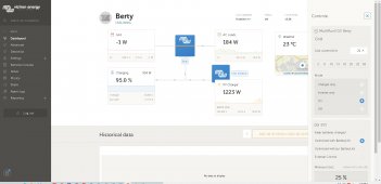
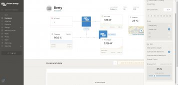
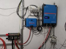
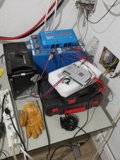
Now i managed to install and connect all my Victron solar gears
Victron MULTIPLUS-II 48/5000/70-50 GX
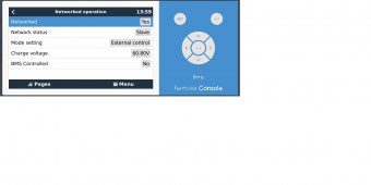
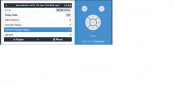
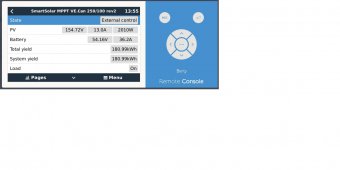
Victron Energy SmartSolar MPPT 250/100 VE.Can
Victron Energy Lynx Power In
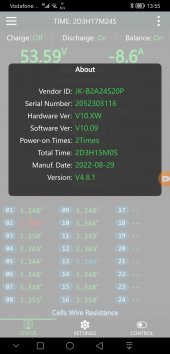
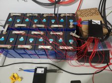
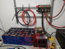
and added JK-BMS B2A24S20P on the 16 x 304ah 3.2v prismatic lifepo4 battery cell
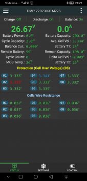
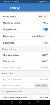
All was fine until one day the sun God decided to show his power") Charge limit in the BMS is set to 100A and the charge controller can do 100A so charging was done at 75A read with clamp meter
Charge limit in the BMS is set to 100A and the charge controller can do 100A so charging was done at 75A read with clamp meter
All OK but when it come to stop charging because of cell OVP reached please watch video and please give me 2-5min from your preciouses time write your opinion.
Yes seller cannot see where is the problem .....
So this happen on Friday and Monday was/is a holyday, so on Thursday when i would return to work (60km from my home) my 16 cells would look like 16 elephant's and imagine the place if would they catch file or exploded due to overcharge
Failed miserably, and if we check the advertising of the product "Never crash -> independent watchdog design " watchdog is sleeping in my case.
well yes i did reset (disconnect and discharge voltage), install the lattes APP set to default by pressing the liFePo4 button,
well now that I'm writing what I done the reset switch is what i did not used,
but let me have my doubts that this will change the situation... any way on Thursday will be done
Charging with max 5A and discharging with no more then 25
Now i managed to install and connect all my Victron solar gears
Victron MULTIPLUS-II 48/5000/70-50 GX
Victron Energy SmartSolar MPPT 250/100 VE.Can
Victron Energy Lynx Power In
and added JK-BMS B2A24S20P on the 16 x 304ah 3.2v prismatic lifepo4 battery cell
All was fine until one day the sun God decided to show his power
Charge limit in the BMS is set to 100A and the charge controller can do 100A so charging was done at 75A read with clamp meter All OK but when it come to stop charging because of cell OVP reached please watch video and please give me 2-5min from your preciouses time write your opinion.
Yes seller cannot see where is the problem .....
So this happen on Friday and Monday was/is a holyday, so on Thursday when i would return to work (60km from my home) my 16 cells would look like 16 elephant's and imagine the place if would they catch file or exploded due to overcharge
Failed miserably, and if we check the advertising of the product "Never crash -> independent watchdog design " watchdog is sleeping in my case.
well yes i did reset (disconnect and discharge voltage), install the lattes APP set to default by pressing the liFePo4 button,
well now that I'm writing what I done the reset switch is what i did not used,
but let me have my doubts that this will change the situation... any way on Thursday will be done
Last edited: