hwse
Solar Enthusiast
- Joined
- Jan 2, 2021
- Messages
- 585
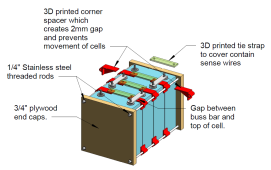
I am designing some spacers for the fixture for my cells and also need to know how big the gap is between the top of the cell and the bottom of the buss bars on the threaded stud and the threaded screw-in terminal studs. I am 3-d printing spacers that will create a 2mm gap between each sell while keeping them from moving in a boat so that the vibration stress is not on the terminals. By placing them this way, the fixture is only on the edge of the top and bottom where the aluminum case is supported on three edges. Right now, the corner spacers have a 4mm tall flange that sits on top of the cell and extends beyond the terminals. I need to know if there will be more than a 4mm gap under the buss bars.
Attachments
Last edited: