diy solar

diy solar

Hello all, and welcome to my Hybrid LFP/LA Project

Mariner62

New Member
Joined
Dec 29, 2020
Messages
84
Happy New Year All,

Thanks for signing me up to the group.

I'm starting a little project to investigate a hybrid Lead Acid/LiFePO4 (LA/LFP) battery bank for my boat. If it works as I hope, I intend to replace the existing 24V/600AH AGM battery bank on my boat with a 24V/560Ah LFP + 24V/110Ah LA bank, but before I get to that I'm going to build and test a "scale model" test system comprising 12V/280Ah LFP + 60Ah LA. A couple of diagrams are attached of the test system and the eventual boat installation.

I have some specific reasons for wanting a hybrid installation, so I don't really want to discuss the "why hybrid" question (unless someone is really interested in that). However, I'm interested in any feedback on the operation of the system, especially things I can investigate through the testing process.

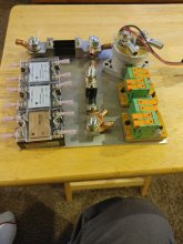
The test system uses 4xEve 280Ah cells, REC Active BMS with shunt and contactor as the LFP component, and a 60Ah AGM with its own Victron Smart Shunt. I also have a Victron 12V/500W Multiplus Invertor and a Cerbo GX for testing.

I ordered the EVE 280Ah cells from China via Amazon some weeks ago and they arrived into Sydney (home) within a couple of weeks, but have now been stuck for almost the same time in the local courier delivery company, Aramex/Fastway, who are just hopeless. Fingers crossed they arrive soon and I can get onto balancing them and building the LFP battery.

One dilemma I have at the moment is how to configure the changeover between Lead Acid (LA) and LFP.

I could configure the LFP isolator to open immediately upon say 90-95% charge of the LFP bank, and configure the system chargers for a Lead Acid profile (with LFP max voltages observed). That way the LA batteries get charged fully every time the system comes to 100%, and operate in float until charging sources dwindle. Then I need a reliable way to bring the LFP battery back online to take the load.

Another approach would be to keep the LA battery in reserve for the majority of the time and manage the charging sources to turn them off when the LFP reaches 90-95%, then the LFP immediately starts to discharge again. Maybe bring the charge sources back at 85% or something like that? This is a more complicated interconnection problem, but certainly doable. In this mode of operation the LA battery never really attains a full charge in normal life, but is never really discharged either. It is just always there to take the load in emergency if (when?) the LFP flips out, or when needed on-line as a long term float when the boat is in storage.

Anyway, that's the plans right now. I'm really interested to hear about any experiences playing with directly connected hybrid systems like in the attached diagrams.

Cheers all
 

Attachments

  • Test Configuration 2.pdf
    147.3 KB · Views: 20
  • DC Power Schematic 1.pdf
    169.7 KB · Views: 15
Last edited:
Happy New Year & Welcome to the forums!

Probably the biggest thing to be aware of when combining different
chemistries is they operate at different voltages and voltage change
over capacity is different.

You can see in the table to the right that if you only charge the lithium
up to the max lead acid (56V in this 48V battery example), then the
lithium batteries are only at 10% charge.

With an isolator you can keep the two systems separate, but they'll each
need their own dedicated charging systems. I'd use a double-throw
double-pole rather than the isolator used in your diagram. The way it
is now, when the lithium was turned "on" it would damage the AGMs.
You'd also want breakers off each of the batteries for protection.
 
How about having lithium battery configured for higher voltage (48V) and charged by PV panels,
Use lead-acid batteries for all loads,
Wire a charge controller fed by lithium to charge lead-acid.

That way, lead acid batteries are always fully charged, more like starting battery service. They supply heavy currents when needed and lithium is the reservoir of power because it is fine at lower state of charge.

This is what I might want to do if I added lithium to my grid-backup system, which has AGM on Sunny Island.
One guy used a Midnight charge controller fed by his EV's 200V battery.
I would connect the battery to a Sunny Boy, because it's output can be managed by Sunny Island.
 
I have a hybrid system. I suggest that you look into massive in rush mainly during
connection. I find that the LFP sucks up the amps from solar and the FLA gets trickle charged day and night. Under a heavy load my FLA assists when the SOC is lower. I would suggest that you have current meters on both banks to watch the relationship between them.
 
Happy New Year & Welcome to the forums!

Probably the biggest thing to be aware of when combining different
chemistries is they operate at different voltages and voltage change
over capacity is different.

You can see in the table to the right that if you only charge the lithium
up to the max lead acid (56V in this 48V battery example), then the
lithium batteries are only at 10% charge.

With an isolator you can keep the two systems separate, but they'll each
need their own dedicated charging systems. I'd use a double-throw
double-pole rather than the isolator used in your diagram. The way it
is now, when the lithium was turned "on" it would damage the AGMs.
You'd also want breakers off each of the batteries for protection.
1609570467402.png
Thanks svetz,
At the moment I'm playing with 12V system and the boat is a 24V system so I'm more comfortable talking about these voltages. This picture shown here is a 20h discharge cycle of my test LA battery. So it starts on float at 13.8V then when I take it off float and apply a 0.05C load (3 Amps) it drops immediately to 13.2V then ramps down from there. This test disconnects the load at 11.0V.

So my thinking based on this is that if I have both LFP and LA connected together, starting from fully charged, the LFP will stay up close to 13.2V for a long time, and will therefor supply the vast majority of the load. I think the LA shouldn't even discharge much. It is effectively on float at 13.2V, powered by the LFP bank!

However, I get what you are saying that if the LA gets discharged but the LFP is fully charged there is a big potential mismatch between the two batteries and ... hmmm! I guess I'm thinking that the LFP doesn't get disconnected much, so the vast majority of the time the voltages MUST be the same since they are directly connected. If they never ever got disconnected and the LFP cycled between say 13.5 and 12.8V then the LA would pretty much always just be on float.

Based on your feedback, I need to be really careful about the re-connection process on the rare occasion when they get disconnected as they could end up at very different voltages, regardless of whether the system is 12 or even 12V nominal.
 
How about having lithium battery configured for higher voltage (48V) and charged by PV panels,
Use lead-acid batteries for all loads,
Wire a charge controller fed by lithium to charge lead-acid.

That way, lead acid batteries are always fully charged, more like starting battery service. They supply heavy currents when needed and lithium is the reservoir of power because it is fine at lower state of charge.

This is what I might want to do if I added lithium to my grid-backup system, which has AGM on Sunny Island.
One guy used a Midnight charge controller fed by his EV's 200V battery.
I would connect the battery to a Sunny Boy, because it's output can be managed by Sunny Island.
So, use 48V on the LFP bank and 24V on the LA? The problem is that all my charging sources are currently 24V, too much expense to change.
However your idea still works with 24V LFP separated with a DC-DC charger.

I think the problem with that will be my Bowthruster. It draws in the region of 450A from 24V. I was thinking that this would power up nicely from the LFP+LA bank together (or even just the LFP), but would not be good just on the 110Ah LA battery. Although, adding another two LA batteries to the LA bank may be a possibility. There is space, and strangely enough, weight is my friend in the boat installation because changing to LFP reduces the overall battery weight and the balance of the boat is adversely affected. (And everyone says lighter weight is an advantage of LFP ,.. not in this case :)
 
I have a hybrid system. I suggest that you look into massive in rush mainly during
connection. I find that the LFP sucks up the amps from solar and the FLA gets trickle charged day and night. Under a heavy load my FLA assists when the SOC is lower. I would suggest that you have current meters on both banks to watch the relationship between them.
Hi Grizzman,
Great point, and lines up nicely with what svetz said too... when disconnected the two battery types can get out of whack voltage-wise, and when re-connecting it could be a big in-rush. I plan to have a shunt on each battery type so I can see how much charge each is taking/giving on a permanent basis.

Do you always leave your LFP and LA connected together? Any circumstance that you need to disconnect them in normal life? If you do disconnect for a while, do you try to fully charge the LA before re-connecting - I guess thats lowest risk ?
 
I keep them connected only while boon-docking. I let the factory converter float the FLA between trips and the solar takes care of the LFP. I bring the FLA voltage up during connection. I have a bank of super caps that I plan on using for this for connection. Due to a SOC error, I have had the BMS disconnect. However the drip coffee kept on brewing (should be a law NOT to mess with coffee)
 
Happy New Year & Welcome to the forums!

Probably the biggest thing to be aware of when combining different
chemistries is they operate at different voltages and voltage change
over capacity is different.

You can see in the table to the right that if you only charge the lithium
up to the max lead acid (56V in this 48V battery example), then the
lithium batteries are only at 10% charge.

With an isolator you can keep the two systems separate, but they'll each
need their own dedicated charging systems. I'd use a double-throw
double-pole rather than the isolator used in your diagram. The way it
is now, when the lithium was turned "on" it would damage the AGMs.
You'd also want breakers off each of the batteries for protection.
Svetz,
this is not correct: a flooded 48V LAB wants 58,4V for a full charge, an AGM wants 57,6V. As you see this range is similar to what the LFP wants for a 100% SOC charge.
 
I have a hybrid system. I suggest that you look into massive in rush mainly during
connection. I find that the LFP sucks up the amps from solar and the FLA gets trickle charged day and night. Under a heavy load my FLA assists when the SOC is lower. I would suggest that you have current meters on both banks to watch the relationship between them.
Hi grizzman,
sounds plausible. Can you show a diagram of your system? I am planning to do a similar one, but I am planning to use a BMS that has charge current limiting like the Electrodacus SBMS0. Looks great!
 
Hi grizzman,
sounds plausible. Can you show a diagram of your system? I am planning to do a similar one, but I am planning to use a BMS that has charge current limiting like the Electrodacus SBMS0. Looks great!
My last BMS was a Chargery. While in "storage" mode the ARM prossessor turned into a heater. Lucky for me I caught it before it drained the PAC.
I do not currently have a diagram on this setup.
Here is a teaser.
 

Attachments

  • 0222211858.jpg
    0222211858.jpg
    127.8 KB · Views: 18
@grizzman
I thought of using the SBMS0 Electrodacus BMS which should allow for the settings needed.
Do you keep the LFP and the LA always connected?
That setup should work nicely.
I am thinking of using that kind of setup in a marine system: the LA and LFP would remain connected in parallel .
Have you ever tested such a system for current between the batteries / batteries to charger?
My guess is that it should work great. I would set LFP charging voltage range 12,6V-13,4V. That will keep the LA battery almost full and floating most of the time. On charge the LFP would charge first and on discharge first aswell. The LA serves mainly as a fallback battery if the BMS fails and to facilitate direct alternator charging.
 
The data isn't mine, the image is a link to the source.
@svetz
check the data again (the big detailed curves, not the one at the right) https://docs.google.com/spreadsheet...LTXYv_1LlbcFqE4gxMgK8SrMvs/edit#gid=968848831

you will find that the charge voltage ranges overlap 100%.

If you cycle your LFP from 15%-90% or in the range of 12.6V-13.4V you fall exactly in the LA charging range in a way that will keep your LA battery happy because it's mostly kept floating (including a low voltage disconnect at 12.6V. The BMS will cut in and cut out of charging at its voltage limits. The charger can be set at 14.2V for the absorption and at 13.8 for the float.

Who has tested that in the real world does confirm it works fine! check: https://community.victronenergy.com/questions/19981/mixing-lead-acid-and-lithium.html

mattybeshara
I have been experimenting with parallel wiring a 140ah fusion LifePo4 and a full river AGM 105ah.
The results are very interesting. Using 2 x Bmv712 shunts I can see the discharge between the AGM and LifePo4 accurately. Both batteries start discharging at 100% SOC
When a discharge of 80ah was applied, 62ah came from the LifePo4 and the remainder from the AGM.
This was also replicated during a charge of 80ah.
The LifePo4 took most of the current all the way until 100% then the AGM was held in absorption stage until it reached 100%.
I’m finding a resting voltage of LifePo4 of 3.2v per cell (12.8v total) is holding the AGM at a float voltage.
As the load disconnects the LiFePo4 spills current into the AGM topping it back up to 100% or just above 12.8v.
Interestingly the LFP discharged first and charges first. It also holds the AGM at 100% until the LifePo4 has depleted which then you will notice the AGM takes over noting the severe voltage sag when loads are applied.

There's even a LFP battery on the market meant to be wired in parallel:
https://www.bos-ag.com/products/le300-smart-battery-system/
 
@grizzman
I thought of using the SBMS0 Electrodacus BMS which should allow for the settings needed.
Do you keep the LFP and the LA always connected?
That setup should work nicely.
I am thinking of using that kind of setup in a marine system: the LA and LFP would remain connected in parallel .
Have you ever tested such a system for current between the batteries / batteries to charger?
My guess is that it should work great. I would set LFP charging voltage range 12,6V-13,4V. That will keep the LA battery almost full and floating most of the time. On charge the LFP would charge first and on discharge first aswell. The LA serves mainly as a fallback battery if the BMS fails and to facilitate direct alternator charging.
I thought of using the SBMS0 Electrodacus BMS which should allow for the settings needed.
Agreed.
Do you keep the LFP and the LA always connected?
No. with that said, I would not hesitate to do so.
Have you ever tested such a system for current between the batteries / batteries to charger?

Yes. In fact, with heavy loads I have observed "load sharing" that reduces as the FLA banks surface charge is consumed. At night the LFP bank "trickle charges" the FLA bank at a few hundred milliamps an hour.
My guess is that it should work great. I would set LFP charging voltage range 12,6V-13,4V. That will keep the LA battery almost full and floating most of the time. On charge the LFP would charge first and on discharge first as well. The LA serves mainly as a fallback battery if the BMS fails and to facilitate direct alternator charging.

Below is a voltage graph of early morning charging. The Chargery BMS Disconnects due to a SOC error. Then the V notch before the voltage drop was when I turned on the inverter. At this point the FLA bank was brewing the coffee. The jump in voltage was when I got the LFP bank back on line.
graph.jpg
 
Hi grizzman,
Nice graph! How did you log that?
I guess the 14,5V is coming from your alternator bulk charging the LA battery. What happened at 7 o'clock when the voltage drops to 13,5V? The BMS appear to connect as they are supposed to do. However at 7:15h what's happening? The BMS seems to disconnect the LFP and the LAB can't take the load. The voltage breaks down but recovers some minutes later in two steps to 13,2V. Here the LFP seems to be back in business. It seems your BMS is NOT reliable. You will shorten your LA bettery's life heavily with this kind of BMS behaviour. I would change that BMS for something more reliable. If your BMS hadn't broken down you'd not really put mmuch load on the LA battery that stays floating under load until the BMS breaks down. It looks to me that the two batteries go evry well together in parallel provided you have a 100% reliable BMS.
 

Nice graph! How did you log that?
Lascar EL-USB-2 Data logger. The software allows analyzation, set up etc. The graph is over an hour long. Zoomed in from a one week recording.
as an example max. voltage was 14.4.

At about 7:00 AM the BMS disconnected (This was due to a software issue in the Chargery BMS. At 7:12 AM I switched the Inverter on. At 7:16 AM
I turned on the coffee pot. At 7:19 AM I got the Chargery BMS back on line. The coffee pot was pulling 75 amps during brewing. This graph was from last spring. The Chargery is no more. The ElectroDacus is on BMS duty now.
 
I am curious about both the hybrid and Electrodacus aspects, but was reading another thread and it did not seem to be keeping track accurately and allowed overcharge. What is your present thinking on using that BMS with a hybrid setup?
 
Well I'm still in the testing stage with the ElectroDacus I am impressed. The voltages test with in a 2-3 mV of my https://moosh.im/mooshimeter/
I have been able to adjust the shunt values to be spot on. (Have you heard "Garbage in Garbage out"?) My guess is lack of attention to the details likely the cause of most inaccuracies with this equipment.
I have the diversion set up to send excess power to the Bogart SC2030 SCC with its own battery management system. Both will be monitored through WiFi.
 
Back
Top