diy solar

diy solar

Help/Critique of RV System, Wire/Connectors

Hey I'm fine w it too, that was my original answer. HOWEVER at 3 in the morning I then saw a post by an admin saying otherwise so I did some rethinking and big long edit. I want my sleep back now!

What is this, rev 3 of your drawing I've downloaded? If I can ever finally get a system designed I'm gonna plagiarize the hell out of it. : D
Hey @Boondock Saint, thanks for taking the time. I mean it!

This is like rev 13. I keep tinkering until it's finally built. So if I want to get any sleep, I'll have to have this thing done soon!

Feel free to plagiarize. If you want the original file, I'll be happy to share. I had to make a lot of original drawings, including the Overkill 8S BMS, the busbars, the class T fuse holder, the mini fuse holders, the circuit breakers, the shore power plug... I'll be happy if someone else can benefit from my work.
 
@Boondock Saint, I got your original post via email before you scrapped it and restarted:
Ground is ground. It's what happens between the other side of + that matters. You could have 50 different voltages and paths as long as they don't leak somehow to each other, it's just voltage - potential. How many grounds do you think is already IN your RV end to end?
 
Really like your plan looks really good, only thing is i thought i read in the manual for the Victron 3000/24 that it needed 2/0 all the way to the inverter?
 
Really like your plan looks really good, only thing is i thought i read in the manual for the Victron 3000/24 that it needed 2/0 all the way to the inverter?
Thanks for bringing this up!

I was calculating based on the rating of 3000W, which would be 125A at 24V. I checked the manual, and for the 24|3000-70 (vs the 12|3000) it recommends 50mm (1/0) for under 5 m runs, two for 50mm cables for 5-10m. My battery will be less than 1.5 m from the Multiplus, so 1 cable should suffice, but I should upgrade it to 1/0 from 2 AWG. (The 24|3000-70's peak power rating is 6000W, or 250A, so while that should only last a few seconds at a time, 1/0 is definitely a safer bet.)

The manual also recommends a 300A fuse. I'd like to upsize from a 200A breaker to a 300A, but I only see no-name Chinese breakers rated at 300A; Blue Sea only seems to go to 200A. Any suggestions on high quality circuit breakers good for 300A?
 
The manual also recommends a 300A fuse. I'd like to upsize from a 200A breaker to a 300A, but I only see no-name Chinese breakers rated at 300A; Blue Sea only seems to go to 200A. Any suggestions on high quality circuit breakers good for 300A?

Midnite Solar has a good selection of higher end breakers. Be careful to not get a polarized breaker for the Inverter/Charger.

 
Shaping up nicely.
Q: Why 100A breaker for 50A Solar controller? Why not 60A to better protect from failures?
GNDS: My slide out also connects to chassis gnd. Same for frig and water heater. Battery is chasis grounded for the breakaway brakes. It throws off my shunt reading a little. I'm using the LA on the tongue for backup.
I didn't want to risk cutting off charging amperage in peak sun. Am I nuts?
 
I didn't want to risk cutting off charging amperage in peak sun. Am I nuts?
SC has a DC-DC converter inside and it's Toroid saturation limits the current output. Very likely the electronic controls will also limit the current to prevent overheating. Which is why you can overpanel.
I have the same SCC, but only 500W solar, so I never hit 50A. Do wish I bought a higher input voltage model.
 
BTW: I saw the breakers you have on the solar panels. I have a pair too. They are rated for DC, which can arc. AC only breakers should be avoided. The wires pullout of these breakers very easily. Maybe the wires need a crimp cap on them. Maybe some solder.
 
Redundant? You have a 12v Chassis battery with a 20A DC-DC charger. Nice, very nice. Do you really need the 24v-12v converter for the 12v backbone? Why not use the 12v battery?
Largest normal load on mine is the furnace 12v blower at 7.5A. Occasional load is my slide out with 20A auto-reset breaker. No problem for a battery, whats your 24v-12v converter rated?
 
Thanks, but I don't see anything above 250A there. Might have to go with fuses.

You don't NEED a 300 amp fuse/breaker - that's just the suggested max. You can go lower if your loads won't exceed the fuse ratings (well, build in the 80% factor).
 
if you install this driver on the cerbu you can use the shunt inside of the bms and get rid of the smart shunt


you can also use the 4A trickle charge output on the multiplus to charge the 12v chassis battery.
 
SC has a DC-DC converter inside and it's Toroid saturation limits the current output. Very likely the electronic controls will also limit the current to prevent overheating. Which is why you can overpanel.
I have the same SCC, but only 500W solar, so I never hit 50A. Do wish I bought a higher input voltage model.
Good point, I think I'll get a 60A breaker. I just wish I had a better idea how much current I'll be expecting on the DC load circuit. I'm hoping to get a DC air conditioner, which will draw 37A, but until then, I probably need a much smaller breaker. Even with it, and the 2.5A a DC refrigerator would draw, 100A might still be too much.
BTW: I saw the breakers you have on the solar panels. I have a pair too. They are rated for DC, which can arc. AC only breakers should be avoided. The wires pullout of these breakers very easily. Maybe the wires need a crimp cap on them. Maybe some solder.
Thanks, that sounds like a pain. Maybe I should get a different breaker more like the Blue Sea 187 series.
Redundant? You have a 12v Chassis battery with a 20A DC-DC charger. Nice, very nice. Do you really need the 24v-12v converter for the 12v backbone? Why not use the 12v battery?
Largest normal load on mine is the furnace 12v blower at 7.5A. Occasional load is my slide out with 20A auto-reset breaker. No problem for a battery, whats your 24v-12v converter rated?
I don't know, the coach came with a 2-battery lead acid house battery bank, and I'm not reducing any of the loads, so I doubt the chassis battery would be a suitable replacement. I'm nixing the Victron 24/12-30 DC-DC charger (it cost about double what I thought) in favor of an Amp-L-Start. But the trickle charge option on the Multiplus suggested by @ed1380 sounds even better.
if you install this driver on the cerbu you can use the shunt inside of the bms and get rid of the smart shunt


you can also use the 4A trickle charge output on the multiplus to charge the 12v chassis battery.
This looks amazing! And it supports the Overkill BMS I bought. Wonder how accurate the Overkill BMS is as a current measuring device compared to the Smart Shunt? Now I wish I hadn't already bought the Smart Shunt. Maybe I'll sell it.

Do I even need the Battery Protect? I know the BMS shuts off charging based on temperature as well as shutting down for low voltage. Does it use onboard FETs to do this? I know some like the Electrodacus SBMS trigger relays to do it.

Thanks for the pointer on the trickle charge option. I'd read about it but forgot. I'll do a bit more research.
Look at the Class T fuses that Blue Sea has.
I already have a Blue Sea 400A for the battery. I was going to go w/ the Victron "Lynx Power In" to clean up my layout since I was using external circuit breakers. But if I need fuses I might just go with the Lynx DC Distributor instead and get their Mega fuses. In the interest of streamlining I would like to standardize on one kind of fuse.
 
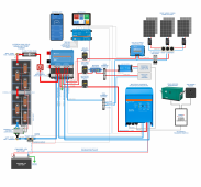
Hopefully getting close to the final version of the diagram/schematic.Winnebago Via Electrical Solar Wiring Diagram Lynx 2021-05-18.png
I needed one extra negative compared to positive connections because of the MultiPlus's Case Ground, so I joined the 24V load negative and the SCC negative at the small negative busbar and ran a fatter negative wire from there to the Lynx Power In.

Another question: I'm pretty sure the 12V load negative returns to the DC-DC converter, but is there a 24V negative that connects somewhere? The DC-DC converter only has an input +, output +, and negative (0V).

Thanks for your input.
 
Every time I think I'm about ready to build, there's more stuff to do:
1. Lugs for the various sizes of posts and wire
2. Lugs for the BMS balance leads
3. Wire

Still trying to find the right PV breaker isolator, plus breakers for the solar panel strings; these will be under the panels, so they need to be very hardy.

Would my installer have all this stuff? Wire, lugs, etc.? I know this is a DIY forum but I'm using an RV technician.
 
Either he does or he doesn't. If you buy it, you'll save money and have spares. If he buys it, you'll pay more and he keeps spares.
 
Hopefully getting close to the final version of the diagram/schematic.View attachment 49546
I needed one extra negative compared to positive connections because of the MultiPlus's Case Ground, so I joined the 24V load negative and the SCC negative at the small negative busbar and ran a fatter negative wire from there to the Lynx Power In.

Another question: I'm pretty sure the 12V load negative returns to the DC-DC converter, but is there a 24V negative that connects somewhere? The DC-DC converter only has an input +, output +, and negative (0V).

Thanks for your input.
The negative on this DC-DC converter is not a load power return. It's a reference and power for the converter. I would tie it to the neg busbar. I would also tie the 12v load return to the neg busbar.
 
Back
Top