diy solar

diy solar

Help/Critique of RV System, Wire/Connectors

Hey brother, if you're gonna spend that much money on a fancy busbur set, it better be functional AND look fabulous on the Victron Red Carpet!
 
Looked at the Amp-l-start. It does not boost voltage, so 12v in - 12v out. Your 24-12v converter should have a voltage adjustment, depending on model.
 
Also curious how you will mount switch and shunt with victron bus. They have different heights and need to be secured for road vibration.
 
Never mind. My post was on an earlier diagram and doesn't apply to the latest.
 
Also curious how you will mount switch and shunt with victron bus. They have different heights and need to be secured for road vibration.
Yes, the shunt ends up about 1/4" lower and the switch is about 3/8" too high, so in my case I just mill out a depression for the shunt and cut an aluminum spacer plate for the switch...
 
Looked at the Amp-l-start. It does not boost voltage, so 12v in - 12v out. Your 24-12v converter should have a voltage adjustment, depending on model.
Yes, I have the Orion 24-12/70 which is adjustable between 10V and 15V. I'll set it to 14.6 for charging the chassis lead acid battery.

Or… I could replace the lead acid chassis battery with a 280 Ah 4S LiFePO4 battery; I have another new 280 Ah 4S setup I was going to put in my old rig, but if I replaced my chassis battery with it, I could run the 12V house loads on the 280Ah 4S chassis battery, and the inverter and 24V loads off the 24V 280Ah 8S house battery. This would give me a total of 11 kWh of battery capacity. This would let me ditch the 24-12 converter and its 92% efficiency, but I would have to upgrade the alternator, add another solar charge controller and 600W of panels. (I thought of using a 24-12 DC-DC charger but it's even less efficient: 88%.)

Or... I could just leave the chassis battery alone. :)
Also curious how you will mount switch and shunt with victron bus. They have different heights and need to be secured for road vibration.
I see @Screwball answered this one, since I haven't actually bought my switches. I think I would rather mount the Power In to a plywood spacer board with rubber bushings so the shunt can sit flush rather than inset, and use a higher spacer for the switch. Do you think that'll work, Screwball?
 
I just ordered a second Lynx to piggyback onto the first one (ran out of busbar/fuse space ?) so I don't want to space up all them mounting holes ... my "electronics closet" has 1.25" thick walls (1/2" ply base clad with glued-on 3/4 t&g pine) so sinking the shunt into the ply is not much of an effort ?
 
Sorry I've been gone for a while, put the system on the back burner. But it's back on the front burner thanks to necessity.

First, thanks to all who contributed to helping firm up my PV battery system.

Second, I’m switching to a 12V battery. I was decided on 24V, bought all my stuff to build it (Victron 24|3000|70 + SmartSolar 100|50 + 6 x 200W 24V panels + 8S 280A 24V bank). But now I'm glad I didn't install it.

So we're on an RV trip now in our 2018 Winnebago Via with the stock 12V 80Ah x 2 house bank. Last Monday, on night 3 of our 2.5 week vacation, our coach lights started to dim, batt. voltage <12. We'd been plugged into shore power for 24 hrs, so suspected converter or fuse fail. Thank goodness I was able to find a great technician who was able to come right away on our 4th try (first 3 were booked weeks into the future). He found the problem right away: the power wire had fallen out of the converter and was a couple of inches away from the contact. I'd missed that. I tried to charge using the alternator, but our chassis battery was also dead. We'd bought a new battery but put off installing until after the trip since the battery boost always got the engine started. Shoulda brought the battery with us.

Moral of the story is we were dead in the water, our coach was bricked. No hot water (electronic ignition), no lights, no carbon monoxide monitor, no fans, even our stock 100W solar panel wouldn't charge because the voltage was too low. I never want to be stuck like that again. And next time it could be just a fluke loose wire, but it could also be almost anything and we could be completely stranded with a single dead component: the single 24V battery OR BMS, fuse, loose wiring, etc. It's literally almost anything in the electrical system that can leave us stranded.

So I'm switching back to a 12V system. (Some have suggested on other threads to have 2 24V batteries for redundancy; but I chose 280 Ah cells (huge cells), so I don’t have room for, nor do I need, 560 Ah of 24V storage (15 kWh). I do have enough cells for three (3) 12V 4S batteries, each with its own 120A Overkill BMS, so in parallel, I would literally have to have all 3 BMSes and/or batteries fail for us to be completely dead.

I love that with a 12V system, I can charge the chassis battery with the alternator, start the engine with the house battery (battery boost), and not have to convert from 24V to 12V to have usable power.

Also, there are DC refrigerators, freezers and air conditioners that are dual 12/24V, but when it's only available in one voltage, it's always 12V (like the Dometic RTX 2000 12V DC air conditioner).

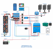
I’ve attached the latest iteration of my schematic. If you’ve got the time, please help me finally finalize my system and build it. I’d like help with:
  1. any input on making my system more robust/foolproof/simpler;
  2. specifics on wiring 3 separate SmartSolar 100/30’s (in parallel?);
  3. specifics on wiring dual Tr Smart 12|12|30 non-isolated DC-DC charger between alternator and batteries
  4. help on maintaining the chassis-house battery bridging/boost solenoid for additional redundancy
  5. also ways to turn alternator charging off to house batteries if good solar production happening
Thanks a million!
 

Attachments

  • Winnebago Via Electrical Solar Wiring Diagram 12V 2021-10-02.png
    Winnebago Via Electrical Solar Wiring Diagram 12V 2021-10-02.png
    555.6 KB · Views: 13
Using equal length cables, I would wire the batteries to bus bars and then the Class T fuse on the positive side and the shunt on the negative side. There is a recommendation that each battery gets its own fuse. Not many do that, but it's a good idea.

The three solar charge controllers can be connected in parallel. Have you considered a 2s3p configuration with a slightly larger controller? A single controller might be less expensive.
Thank you, @HRTKD!

So you mean connect the batteries in parallel using bus bars rather than directly wiring them in parallel, correct? That sounds like a great idea. Separate fuses sounds safer, too. But it also sounds like a nightmare in terms of the number of different fuses I have to carry spares of! But seriously, sounds good.

I think I need 90 amps of SCC for 1200W now that I'm down to 12V batteries. That is a monster charger (Victron 250/100 is $1K vs three 100/30's is $157 x 3 = $471). Plus failure of a single SCC could cut short any boondocking trip we may be on, but if one of 3 SCCs fails, we can finish our trip, we just have to be cautious with our electricity use.
 
I won't say that Victron equipment is 100% reliable but it's darn close.

I looked back through four pages of posts and couldn't find the specs on your solar panels. Can you post that? Have you used the Victron MPPT calculator?
 
I won't say that Victron equipment is 100% reliable but it's darn close.

I looked back through four pages of posts and couldn't find the specs on your solar panels. Can you post that? Have you used the Victron MPPT calculator?
I'm using 200W 24V Newpowa panels x 6.
 
We need the real specs. Voc, Imp, Isc, etc. It's the label on the back of the panels usually. A link to your panels will do if the full specs are there.
Sorry, I thought I successfully uploaded the spec sheet. I'm camped at Wahweap Campground at Lake Powell, 0-1 bar with T-mobile and the campground's satellite internet guest wifi is terrible with good weather, we were having hailstorms yesterday. I've re-uploaded the spec sheet (EDIT: upload failed), but here are the main specs:

Vmp 34V
Imp 5.88A
Voc 40.46V
Isc 6.23A

So I was planning on running 3 2s strings, so each 100/30 would need to output 30A or less above 13.2V, but since LiFePO4 charge voltages are 13.6 or higher above 10% SOC, and I shouldn't be below 10% anyway, it should be fine. Yes?

EDIT: Since I can't seem to upload the file, and I can't find the panel on Newpowa's website, let me know if you need additional specs. Thanks!
 
Last edited:
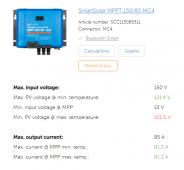
I plugged your specs into the Victron MPPT Calculator and it recommends the 150/85 using either a 3s2p or 2s3p PV configuration. The image below is for 3s2p. I know you're looking for redundancy. You can always buy a second solar charge controller and bring it along.

3s2p is easier to wire up and requires no fusing between the strings. Once you go to three strings you need to add fusing.

1633584732586.png
 
I plugged your specs into the Victron MPPT Calculator and it recommends the 150/85 using either a 3s2p or 2s3p PV configuration. The image below is for 3s2p. I know you're looking for redundancy. You can always buy a second solar charge controller and bring it along.

3s2p is easier to wire up and requires no fusing between the strings. Once you go to three strings you need to add fusing.

View attachment 67848
Thank you! That's amazing. I've tried the Victron calculator before, but couldn't quite figure it out. I'll try playing with it again.

Costwise, the 150/85 ($560) is a lot less than the 250/100 (~$1K). But it's pretty close to 3 x 100/30's (about $120 more than $147 x 3 = $441).

What are the benefits of having a single 3s2p vs 3 separate 2s strings besides wiring simplicity? What am I missing?

As for redundancy, it's not crucial, as I will have the alternator as backup, but it would be nice to have redundancy! But a spare 150/85 adds $560 to the system cost, whereas a spare 100/30 only adds $147. Plus, 3 + 1 spare 100/30's cost about $30 more than a single 150/85! Plus even without a spare 100/30, in case one fails, I would lose only 33% of my solar, not 100%.
 
Back
Top