diy solar

diy solar

Help decoding JBD BMS instructions

Simi 60

New Member
Joined
Jul 10, 2021
Messages
159
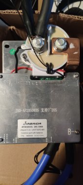
Had my 3 JBD JBD-AP20S003S-P20S-200AB BMSturn up yesterday, description and manual is in this thread


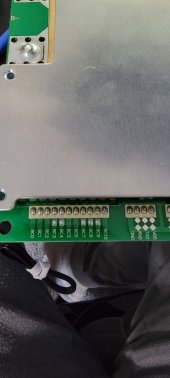
Just a little bit of trouble with the wiring instructions, I THINK I know what it means but just need someone else to confirm before I go any further.
There are way more wires than I need for an 8s but the JBD rep on AB assures me this is the correct one and it will do multiple battery sizes.

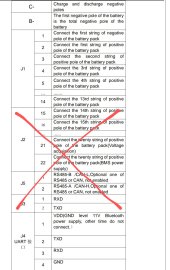
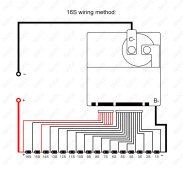
I am thinking it means connect black then 1to 8 then red and the rest of the wires do not apply.
As I am not doing can forget about the section with a cross through it

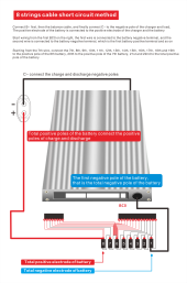
and the last bit, am I really supposed to short those wires? (Circled)
Im guessing that tells it that it's the end of the line?
Am I reading that right?

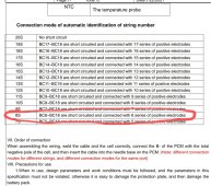
And what is the six series of common electrodes bit???

Thanks
 

Attachments

  • Screenshot_2021-10-30-11-17-12-350_1.jpeg
    Screenshot_2021-10-30-11-17-12-350_1.jpeg
    264.8 KB · Views: 264
  • Screenshot_2021-10-30-11-17-04-120_1.jpeg
    Screenshot_2021-10-30-11-17-04-120_1.jpeg
    143 KB · Views: 239
When I asked for some more information I was sent this, but it hasn't really helped me decode the instructions
 

Attachments

  • 9F1592DA24EF8CC3978F60F84DFB5D73.jpg
    9F1592DA24EF8CC3978F60F84DFB5D73.jpg
    234.8 KB · Views: 428
I have not personally used a JBD, but those instructions are not too bad for a Chinese translation.

The wiring for running 8S is a little odd, but that is how it detects that it is running on only 8 cells.

How I read this is that the negative of cell one probably goes to BC0. Usually the first wire or the only black wire on the first connector.

Cell 1 + goes to BC1, cell 2 + to BC2, cell 3+ to BC3, cell 4+ to BC4, and cell 5+ to BC5. But now it gets odd.

Cell 6+ lead will tie to the BMS leads BC6, BC7, BC8, BC9, BC10, BC11, BC12, BC13, BC14, BC15, BC16, BC17, and BC18

Cell 7+ goes to BC19, and finally, Cell 8+ goes to lead BC20

This agrees with the sheet you sent in the second post as I was typing this. Does this help or is there another question?
 
I have not personally used a JBD, but those instructions are not too bad for a Chinese translation.

The wiring for running 8S is a little odd, but that is how it detects that it is running on only 8 cells.

How I read this is that the negative of cell one probably goes to BC0. Usually the first wire or the only black wire on the first connector.

Cell 1 + goes to BC1, cell 2 + to BC2, cell 3+ to BC3, cell 4+ to BC4, and cell 5+ to BC5. But now it gets odd.
Thanks for that

Cell 6+ lead will tie to the BMS leads BC6, BC7, BC8, BC9, BC10, BC11, BC12, BC13, BC14, BC15, BC16, BC17, and BC18

Cell 7+ goes to BC19, and finally, Cell 8+ goes to lead BC20

This agrees with the sheet you sent in the second post as I was typing this. Does this help or is there another question?
But I have no idea how you came to the above conclusion.
Care to share where it says that?

Thanks
 
Thanks for that


But I have no idea how you came to the above conclusion.
Care to share where it says that?

Thanks

well the instructions are little challenging but for a chinese product, well, thats to be expected and its not really that bad.
If I had to take a guess as to why it seems odd, well...
I am not sure you can call it "odd" as this is a mode to support multiple series configurations with one device and set of connections.
Think of it this way... maybe if they described it in a much longer text blurb such as:

This device has the ability to support series battery configuration from 7S to 20S.
In order to support this functionality the BMS will check for shorted wires on the J1 connector to decode how many series batteries you have when it powers up.
The input balance leads BC5-BC18 are used to configure the BMS by shorting them together and using this bundle as the input for your third highest voltage cell.
Important notes:
you should wire up the connector and verify voltages BEFORE you connect it to the BMS!
Looking at the input table the last two inputs BC20 and BC19 (highest and second highest voltages) must always be used and connected to the highest and second highest voltage battery pack cells.
Consult the table and short together the inputs as shown in the "connection mode table". Once you have shorted these inputs together based on your series cell configuration, this input bundle will be connected to your THIRD highest voltage cell.

The remaining balance lead inputs(BC1 to BCn) will be used in order depending on how many series cells you have
starting with the first cell (lowest voltage).

====
a bit long winded but maybe it helps...sometimes it can be a challenge to try and use firmware changes to support bootup options and avoid adding a hardware switch or complicated startup procedures hehe
 
Thanks for that


But I have no idea how you came to the above conclusion.
Care to share where it says that?

Thanks
From your instruction sheet, you circled the line for 8S setup.

"BC6~BC18 are short circuited and connected with 6 series of positive electrodes"

The first half before the and is... "BC6~BC18 are short circuited" which means... You short together all of the leads from BC6 to BC18

The second half, after the and... "connected with 6 series of positive electrodes"
which means... You then connect that to the positive terminal of the 6th cell.

The bad confusing grammar comes from the automated Chinese to English translation. I am used to that.

From the other instructions and diagrams, you connect the first 5 cells with cell one negative to the BC0, and each positive goes to the BC with the cell number. And the positive terminal of the last 2 cells always connect to BC19 and BC20.

I am pretty sure that BC20 also supplies the power to operate the BMS electronics. But that is not clearly stated anywhere.
 
I was still a bit unsure so I got onto the JBD rep on Alibaba and had a speedy response with pictures which makes it easy and...... not what I was thinking
Zoom in
 

Attachments

  • dab3a40337d0eb11d032fad5b7cf3a32.png
    dab3a40337d0eb11d032fad5b7cf3a32.png
    274.9 KB · Views: 468
I was still a bit unsure so I got onto the JBD rep on Alibaba and had a speedy response with pictures which makes it easy and...... not what I was thinking
Zoom in
I have the exact same BMS and just got it online today. What app are you using @Simi 60
The xiaoxiang app on iOS requires pay to configure, wondering if that is the norm.
 
I don't do apple

I am using the android 3.1.1026 apk
Works a treat it seems.
 

Attachments

  • Screenshot_2021-11-17-08-28-27-035.jpeg
    Screenshot_2021-11-17-08-28-27-035.jpeg
    221.4 KB · Views: 76
Just received my 300 amp Jiabaida with 16 pcs of LiFePo4 cells. I´m about to build 8S and 24V system from them. Do these instructions also apply on this device? I figured out it´s configurable from 7 to 20 cells with the short circuit method described above?

I think the bluetooth is included on that device
 

Attachments

  • IMG_20211228_094005.jpg
    IMG_20211228_094005.jpg
    89.4 KB · Views: 108
So this is my first post so bear with me, however I have a 100A JBD 10S BMS. I wanted to use it for 7s. I went to their website and poked around and found my BMS there, it says it does 7, 8 or 10S. Having a little looksee on the board I noticed if I turn it upside down there's solder points underneath the 10s connector for what appears to be bridging. So I hooked the lead wires up to a test battery pack by connecting the wires that get bridged together (without actually bridging them) and lo and behold, 7s setup working perfectly.
 

Attachments

  • 20220105_115944.jpg
    20220105_115944.jpg
    71.2 KB · Views: 96
I was still a bit unsure so I got onto the JBD rep on Alibaba and had a speedy response with pictures which makes it easy and...... not what I was thinking
Zoom in
Really helpful image. Thanks for sharing it. I had the same question about "shorting" and this clarifies perfectly.
 
Sorry to be late to this thread, but I have one of the 300A variants running in a 16s configuration and I configured it in accordance with the english languange manual posted by OP, and also in accordance with this nice diagram (please see attached picture) provided by QUCC. The QUCC units are just rebranded JBD of course.
I just wanted to add this in hopes that it might be a little more clear to someone, as I found it quite helpful.
 

Attachments

  • Sc3f4bc68dbcb43d0a084f017883d16ceN.jpg
    Sc3f4bc68dbcb43d0a084f017883d16ceN.jpg
    202.6 KB · Views: 207
Sorry to be late to this thread, but I have one of the 300A variants running in a 16s configuration and I configured it in accordance with the english languange manual posted by OP, and also in accordance with this nice diagram (please see attached picture) provided by QUCC. The QUCC units are just rebranded JBD of course.
I just wanted to add this in hopes that it might be a little more clear to someone, as I found it quite helpful.
This is helpful. Just saved me from a mistake. How long have you been running it?
 
Sorry to be late to this thread, but I have one of the 300A variants running in a 16s configuration and I configured it in accordance with the english languange manual posted by OP, and also in accordance with this nice diagram (please see attached picture) provided by QUCC. The QUCC units are just rebranded JBD of course.
I just wanted to add this in hopes that it might be a little more clear to someone, as I found it quite helpful.
This picture solved my problem. Thank you!
 
If I may ask, so some of the wires go to positive terminals and some go to negative? I have the BMS like in Robert Greens post above. Only mine will be 8S.
 
Back
Top