diy solar

diy solar

Help I'm an idiot

Looking good with new drawing :D

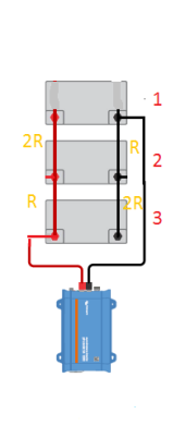
Four unique paths and four unique lengths. Three Cables for Each Length.

1) Cable Length of Battery Positive to Inverter Positive
2) Cable Length of Battery Negative to Inverter Negative
3) Cable Length of Battery Positive to Charger Positive
4) Cable Length of Battery Negative to Charger Negative

1,2,3,4 can each be a different length. but all three cables for each 1,2,3,4 connection need to be the same.

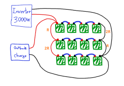
For each connected device (for example, the outback charger) and polarity connection, each wire going to a given battery terminal ought to be the same "length" electrically. The real measured thing is Electrical Resistance, and having equal length of wire of same size and metal with same end connectors is a reliable way of matching this Resistance. With your setup, that means three cables of equal length for each polarity connection and device.
(2 polarities * 2 devices = 4 unique paths) Each unique path needs all cables to be same length. Four unique paths, three cables per path.

Outback charger would have 6 six total cables. 3 for positive, 3 for negative. All 3 positive need to match in length. All 3 negative need to match in length. But the matched positive length and matched negative length can be different.

Hope this helps! Seems like you already got it, looking forward to future updates. Cheers!
 
Hope this isn't too much.

1652130045896.png

"Diagonal" is the type I drew as alternative.
1652130157025.png
"Posts" is the type in updated drawing from original poster.
1652130174467.png
"Busbars" is the type most recently mentioned by @MisterSandals
1652130416976.png

All totally work, just sharing to help with the confusion of "which cable needs to be what length" given a configuration :)
 
Last edited:
The way drawn:
View attachment 94006

Potentially balanced "Diagonal" rewire:
View attachment 94007

if the second one is not actually balanced, someone please correct me and i'll edit this post ??️
If each 4 battery series string is considered to be a single 48 volt battery, then it can be wired as I described here: https://diysolarforum.com/threads/calculation-of-parallel-string-battery-currents.37937/post-487633

All you would have to do to achieve (theoretically) perfect balance is to adjust the resistance of your link cables as shown in this image:

batt7-png.94470


The letter "R" beside the link cables represents the resistance of those link cables, and can be any practical value of a milliohm or less. Two of the link cables are labeled "2R". That means that the resistance of those two should be twice the resistance of the cables labeled "R". A good approximation to this is to make the "2R" cables twice as long as the "R" cables. Doing this is not exact because it doesn't take into account the way the clamp resistance of the lugs at the cable ends (which is constant regardless of the length of a cable) adds to the cable resistance.

Do it like this:

1652121637185-png.94472
 

Attachments

  • Batt7.png
    Batt7.png
    12.4 KB · Views: 45
  • 1652121637185.png
    1652121637185.png
    74.8 KB · Views: 45
Last edited:
That means that the resistance of those two should be twice the resistance of the cables labeled "R". A good approximation to this is to make the "2R" cables twice as long as the "R" cables.
I learned something pretty interesting today! Thanks.
 
Check on the state of charge of your batteries before hooking up. If different, some things to do.
 
Missing from that whole list of stuff is a decent 12v charger that you are going to use to charge each agm up individually first - before you place them into your final solar configuration.

Something you may want to have on hand for a say a yearly preventative maintenance procedure too.

With all those batteries on hand, you'll want about 10-20a charger. If those batteries are old, or have been sitting around, I have a personal recommendation, but maybe you already have something.

NO DINKY maintainers though!
 
Back
Top