Yes.I don't think you have shared the sticker info from your panels.
But assuming the open circuit voltage is 40 volts you should see ~40 volts but 0 amps.
Unless you are using your meter in ampacity mode, is that what you are doing?


You are using an out of date browser. It may not display this or other websites correctly.
You should upgrade or use an alternative browser.
You should upgrade or use an alternative browser.
Help me diagnose my system
- Thread starter McDubsy
- Start date
I'll double check the sticker in the morning and send pics.Something odd there.
40v @ 10 amps would make these 400 watt panels.
How did you measure the current when you did your amperage test on the panels today?
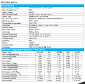
The SCC has an option to manually set the charging levels.We need to know the bulk/absorb and float voltages.
Lithium is a bunch of different chemistries.
It may think you have a battery with max voltage of 12.6 volts.
That would not charge your lfp battery very quickly at all.
batteries, inverter, solar charge controller and the busbars that tie it together.
Will probably ask for wire guages after I see the picture.
I did so based on my batteries specs.
I'll send pics of all of that in the morning.
Okay. Pics coming tomorrow evening.We need to know the bulk/absorb and float voltages.
Lithium is a bunch of different chemistries.
It may think you have a battery with max voltage of 12.6 volts.
That would not charge your lfp battery very quickly at all.
batteries, inverter, solar charge controller and the busbars that tie it together.
Will probably ask for wire guages after I see the picture.
Thanks a ton!
Bud Martin
Solar Wizard
- Joined
- Aug 27, 2020
- Messages
- 4,843
So you have 2s4p configuration for your panels, are you using combiner box or 4-to-1 adapter?
I also agree on testing one string string at a time to see if each string is putting out about the same or not.
I also agree on testing one string string at a time to see if each string is putting out about the same or not.
I'm using a 4 to 1 adapter.so you have 2s4p configuration for your panels, are you using combiner box or 4-to-1 adapter.
I also agree on testing one string string at a time to see if each string is putting out about the same or not.
I'll do the tests tomorrow and post pictures of every aspect of my system.
Thanks a ton for the help!
John Frum
Tell me your problems
- Joined
- Nov 30, 2019
- Messages
- 15,233
Then you should be getting 40 volts * 2 amps * 8 panels = 640 watts into the charge controller.I just did a test like that today and I am getting 40 volts and 2 amps. I have tested each of my eight panels in this manner and the results are identical.
But you getting ~half that.
I love a good mystery.
30 feet give or take.How long is the run from the panel to scc?
John Frum
Tell me your problems
- Joined
- Nov 30, 2019
- Messages
- 15,233
Assuming the pv wire is 10 awg if your panels delivered to spec your voltage drop should be slightly over 3 percent.30 feet give or take.
So your pv wires are not oversized.
I think someone mentioned testing each string separately. I'm curious to see the results.
Yeah, I think the PV cables are 10AWG. After the 4 to 1 adapter I sized up to 2/0 for the run to the SCC. I don't remember why but it made sense at the time.Assuming the pv wire is 10 awg if your panels delivered to spec your voltage drop should be slightly over 3 percent.
So your pv wires are not oversized.
I think someone mentioned testing each string separately. I'm curious to see the results.

I'll confirm that in the morning.
400bird
Solar Wizard
I'd like to see the 4:1 adapter with 2/0 on the output.Yeah, I think the PV cables are 10AWG. After the 4 to 1 adapter I sized up to 2/0 for the run to the SCC. I don't remember why but it made sense at the time.
I'll confirm that in the morning.
Sorry fellas.@McDubsy , you left us hanging.
Pics and accurate stats coming to orrow morning.
It was cloudy today and I had to run out a town.
I'd like to see the 4:1 adapter with 2/0 on the out
Okay Fellas.@McDubsy , you left us hanging.
Here are the accurate specs. I was a bit off.
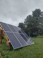
I apologize for the bad lighting in the pics. They system is in the basement of my off grid cabin. This is all run similarly to the system that was here when I bought the place. I have simply been upgrading components. Once I get the system functioning properly, I will re-run the wiring. Here is what I have.
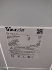
*** 8 Trina Solar panels (Pic)
-325W
-VmP 37.2v
-ImP 8.73v
-VOC 45.6v
-ISC 9.19A
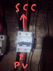
Panels are run in a 2s4p. The 4 in Parallel connect with a 4 to 1 adapter. From that they go to 6AWG to a fuse breaker switch, then from there to 2 AWG to the SCC about 30 feet away. If my math is correct, the max PV output is 74v-36.76a
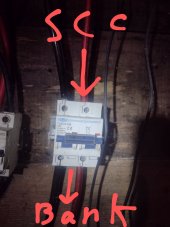
*** I have a DC fuse breaker between the panels and SCC. (Pic)
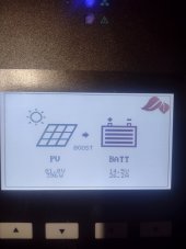
*** Renogy Rover MPPT (Pic)
-Max PV input 150V
-Max PV input 100A
***I have a DC fuse breaker between the SCC and Batteries.(Pic)
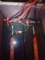
*** Ampere Time batter bank. 2 12-300ah batteries in Parallel (Pic)
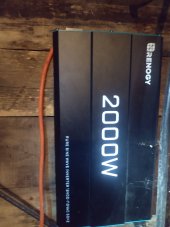
*** Renogy 2000W Inverter(Pic)
-I eventually need to upgrade to at least a 3000W inverter/charger So I can use my generator.
So this morning was cold and cloudy. Lots of ambient light but NO direct sun. The array was producing 300W. Which is very close to what it produces in full sun. (I'm confused) Am I REALLY losing THAT much due to the panel temperature?
So to recap my problem. I get an average of 350W from the panels in full sun. Average high is in the morning and is 500W. My SCC history shows it has gotten as high as 1200w only once.
I am open to ANY suggestions. I am happy to re-run anything or try different components. My fear is that the panels are faulty.
P.S.
I will test each pair of panels the next time I have a sunny day. (unless testing in the cloudiness would provide the needed info??)
Attachments
-
 IMG_20220808_105411863_HDR.jpg218.6 KB · Views: 13
 -
 IMG_20220808_105246694_HDR.jpg90.1 KB · Views: 12
 -
 IMG_20220808_104749072_2.jpg100.6 KB · Views: 12
 -
 IMG_20220808_104732763.jpg105.6 KB · Views: 12
 -
 Rover 100.PNG189.8 KB · Views: 15
 -
 IMG_20220808_104749072_3.jpg104.1 KB · Views: 14
 -
 IMG_20220808_104805780.jpg104.9 KB · Views: 14
 -
 IMG_20220808_104717781.jpg98.4 KB · Views: 14
John Frum
Tell me your problems
- Joined
- Nov 30, 2019
- Messages
- 15,233
It might be elucidating.I will test each pair of panels the next time I have a sunny day. (unless testing in the cloudiness would provide the needed info??)
I say go for it.
Is that car audio cable on the pv run?
I see you are tapping only one end of the battery.
That usually results in uneven charger/discharge between the batteries.
Okay. I will test the panels.It might be elucidating.
I say go for it.
Is that car audio cable on the pv run?
I see you are tapping only one end of the battery.
That usually results in uneven charger/discharge between the batteries.
Yes that is audio wire. I had forgotten about that. I have the correct stuff. I'll swap it out.
By tapping, are you referring to my little clamp on the left positive terminal? That is from an AC charger that I am not running at the moment.
John Frum
Tell me your problems
- Joined
- Nov 30, 2019
- Messages
- 15,233
No I mean the main system wires.Okay. I will test the panels.
Yes that is audio wire. I had forgotten about that. I have the correct stuff. I'll swap it out.
By tapping, are you referring to my little clamp on the left positive terminal? That is from an AC charger that I am not running at the moment.
For batteries in parralel the diagonal pattern is better.
See page 18 of wiring unlimited. -- https://www.victronenergy.com/upload/documents/Wiring-Unlimited-EN.pdf
Never mind I just don't see well.
Similar threads
- Replies
- 2
- Views
- 239
- Replies
- 6
- Views
- 311