diy solar

diy solar

Help Needed: Can I run the output of an MPPT charger to another DC2DC charger with MPPT?

awizemann

New Member
Joined
Sep 26, 2022
Messages
10
The title is a bit ambiguous so let me explain my situation. I have a complete system set up in a Land Rover LR3 for off-grid adventures: a starter lithium-ion battery (antigravity 80ah with jump start) and a house battery (renogy 50ah lithium ion) connected to a renogy dc2dc charger with a solar MPPT connection. I have a hood-mounted 100watt lensun solar panel that works very well with an open voltage of ~26v. That open voltage is my current problem - because the renogy dc2dc maxes out at 25v, I am getting over-voltage errors when the panel is in max sunlight. Rather than messing with voltage converts and or replacing a very well-installed charger, I was wondering if it is possible to use a secondary MPPT charger supplied by the panel manufacturer that can handle the solar open input voltage and connect the output (12 v) to the solar connection of the renogy... I might lose some power from the panel... but it would be way more consistent - I just don't know if you can go MPPT to MPPT like that? Any help here would be appreciated. I am a bit of a newbie to this.

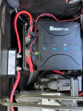
Here is the DC2DC Charger:

Here is the solar panel:

Here is the solar panel MPPT controller:
 
Not sure of the specific hardware, but I expect not.

MPPT output is based on attached battery voltage, and most get their power from the battery. The DC-DC isn't going to power the MPPT on its input, nor will it likely provide a voltage for the MPPT to read.
 
If you have a new MPPT charger that outputs (a charge voltage for) 12V, why do you need to connect it to the DC2DC charger MPPT connection?
 
You're getting closer, but the MPPT is going to try to pull up to 25A out of the converter if the battery can take it, and that will cause the converter to draw as much as it can from the panel causing it's voltage to drop until it drops below the input of the converter. If you could limit the DC-DC output to the battery to never exceed the panel power, you might make it work.

For $15, it's probably worth a try.
 
If you have a new MPPT charger that outputs (a charge voltage for) 12V, why do you need to connect it to the DC2DC charger MPPT connection?

Mainly because I want everything to go through the Renogy DC2DC charger because all my monitoring goes through that, so I can see what state the batteries are in, what is charging them, how much/long they are used/charged for, etc.
 
For the full system, I use this:

And then on the house battery, I use this:
 
For the full system, I use this:

This will only report what passes through the DC-DC.

And then on the house battery, I use this:

But this should also pickup what comes in from the alternate MPPT if connected properly. Connect to load side of shunt, and it will see what's coming from the panel.
 
Yea, I was thinking the same thing, but the entire idea of this set up is for the panel to charge both batteries... so I need to think through this a bit.
 
Yea. Frustrating since it's all mounted and only .5w more... it works, but when it reaches the full potential of charging, it triggers the error. I will try to step it down to see if that fixes it; if not I need to figure out a replacement or just re-route some things. Thanks for your help.
 
Put some power silicon diodes in series with the panel feed, you only need to drop a volt or two, 3 diodes in series.
You will loose a small amount of power but its a very low cost option.
 
Put some power silicon diodes in series with the panel feed, you only need to drop a volt or two, 3 diodes in series.
You will loose a small amount of power but its a very low cost option.

I like the sound of this, but it is WAY out of my wheelhouse. Any chance I can get more guidance on what diodes, how to wire them in, etc? It seems like a single diode will drop 0.6v-1.2v (exactly what I need!). I am just clueless on where and what to get there. I am still researching though...
 
I like the sound of this, but it is WAY out of my wheelhouse. Any chance I can get more guidance on what diodes, how to wire them in, etc? It seems like a single diode will drop 0.6v-1.2v (exactly what I need!). I am just clueless on where and what to get there. I am still researching though...
It is probably simpler than you are thinking.

What I would do is buy a 'full bridge rectifier' because it is basically 4 diodes pre-packaged into a box and gives you the option of running just one, or more than one in series, to attain your desired voltage drop.
for spade terminals
for ring terminals

But, and i know this is going to sound silly.. Have you considered experimenting with tape? I'm pretty sure a small strip of tape applied along one or the other edge of this panel is going to make sure it never hits 26v, and the cost is probably free. Yes, you lose watts but you lose watts with diodes too.
 
The bridge rectifier pack is ideal, remove the positive solar feed from the DCC30, connect the bridge rectifier in series, with the + pin connected to the DCC30 solar input. Connect the solar feed to the - pin on the rectifier. This will give aprox 1.4 volt drop or connect to one of the AC pins for 0.7 volt drop.
As an alternative any diodes rated higher than 5 amps, 50 volts.
 
Success! The bridge rectifier was perfect. Installed according to the instructions above and I am running on solar power now. Although I did lose a volt, the DCC30 seems to be happier and charging at the highest level it has since I set this all up. Here is the install pic. The second photo is the charging status, it’s a foggy day (double what’s shown since the DCC30 splits between the batteries). Thank you to everyone that has helped me here. Hopefully this helps someone else in the future. I’ll check this over the next few days to make sure there isn’t a heat issue or anything, but this seems to feel like a full solve for the over-voltage issue I was having.
 

Attachments

  • D9DFA755-0AED-49CE-95C7-D3FFA379A44D.jpeg
    D9DFA755-0AED-49CE-95C7-D3FFA379A44D.jpeg
    200.2 KB · Views: 8
  • 8C360849-74E4-45FC-8B11-78E42280D958.jpeg
    8C360849-74E4-45FC-8B11-78E42280D958.jpeg
    201 KB · Views: 7
Back
Top