TommyHolly
New Member
- Joined
- Jun 24, 2021
- Messages
- 207
Hello,
Maybe someone can help me please? I suspect that some of my cells are bad. My main goal right now is to test all 48 cells but I'm not sure what is the best way? Wouldn't a capacity test show me a better, more definitive result? (Or does a capacity test on 48 cells take over a month like I was told?)
MY QUESTIONS FOR YOUR GUYS ARE AT THE BOTTOM.... thanks!
SYSTEM SPECS:
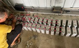
- I bought a 2012 Lagoon 450F sailboat boat down in the country of Panama which had a 12v, 1,200Ah LifePo4 system consisting of 48 CALB-brand cells, (3.2v 100Ah cells).
- The batteries are now about 6 years old, and the former owner, who was not an electrician, designed and installed the system himself.
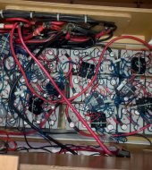
- The original owner connected them first in groups of 4S (4 cells in series), to make twelve, 12v 100Ah batteries. Then he hooked up all twelve batteries in parallel to form a giant 1,200Ah system. Yes, I know that is not how you should connect them.
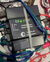
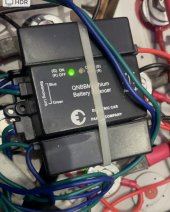
- Each group of 4s batteries had something called a "QNBBM 4S Lithium Battery Balancer" connecting each group of four. But nothing else.
- There was no BMS!! The previous owner bragged those 4S Lithium Battery Balancers were the BMS...ugh
- There was no Smart Shunt or any kind of way to monitor the system when I bought the boat. He used the Xantrex Inverter/Charger monitor which only displays voltage like a volt meter.
- The system is charged by 2,060W of solar panels, through three Outback Solar Charge Controllers (80A + 80A + 60A).
- The system is also charged through shore power through the Lagoon (Lagoon boat manufacturer) French 220v 60A Cristec battery chargers.
- There was a XANTREX 3,000w FSW3012 Inverter/Charger being used ONLY as an Inverter and not as a charger.
I'm pretty sure some of the batteries are bad but I've been getting bad advice from the "Lithium experts" here in the marina. I want to test these to make sure which ones work.
ORIGINAL PROBLEM:
- The original problem was that the entire system would shut off after turning the inverter on for a few minutes with any kind of load 300w to 1,000w
- The Xantrex 3,000w inverter/charger only had the inverter portion connected, the charger wasn't being used. Instead the shore power connects to the 220v 60A Cristec battery chargers.
- The voltage displayed on the Xantrex Monitor or with a voltmeter directly on the batteries would rapidly go down from 13.4v to about 12.7v to 12.9v and then the Xantrex would shut off. This would happen after only 60-120 seconds of operation. Measuring individual cell voltages on the batteries during this time, I would see it start about 3.4v and watch it go down to about 3.1v before it shut off.
THINGS I'VE FIXED AND NOW KNOW FOR SURE:
- I checked the CALB website and see the chart showing that these batteries drop off completely at around 3.15v for a cell. So they were rapidly discharging down to their lower limit of 12.7v.
- I also know now that LiFePo4 batteries shouldn't show much of a voltage drop, they should hold relatively steady and only drop off at the end when they are empty.
- I know that you need a BMS which is connected to all the batteries and not just the individual cells consisting of each 4S battery. So I think those QNBBM 4S Lithium Battery Balancers were useless.
- I know that batteries need to be first connected in Parallel, and then afterwards, connect them in series to make a 12v system. So eventually I'll be making a 12-cell 3.2v 1,200Ah battery (12P), and then connecting 4 of these together in series (4S), to make a 12P 4S 12v 1,200h system
- I purchased and installed a Victron 500A Smart Shunt, it works great on the temporary Lead Acid batteries I installed
- I purchased a DALY 500A LiFePo4 12v 4S Smart BMS and plan on using that when I put back the Lithium Batteries again. I will also hook them up first as four large 3.2v batteries in Parallel, and then connect those four in series to make them 12v.
- One of the Outback 80A solar controllers was bad, I've since replaced it and luckily they replaced it even though it was 2 months out of warranty. The solar system works great now.
- I found quite a few slightly loose connections, as well as a few connectors that weren't properly crimped on or corroded. When I re-install the system, I purchased a 1/4" thick copper bar to connect the cells to. And some new 1/0 AWG "welding wire" cable with new tinned-copper connectors and professional hydraulic crimper to make my own cables with heat shrinks.
- Also there was a leaky hatch directly above the batteries. The previous owner was an ass and tried to use caulk to stop the leak but that didn't work. The batteries were sitting in over 2" inches of water. (Luckily that was too low to reach the connections). But you could tell that water was dripping on top of them because many battery metal washers had signs of light rust or slight green corrosion. None of it was too bad.
- In the meantime, I needed my 12v lights, fans, refrigerators and freezer to work... so after removing the lithium cells, I was forced to purchase eight 160A Deep Cycle Marine lead acid batteries as a temporary measure until I can work out the problems. If the lithium cells are bad, I'll likely purchase two more of these lead acid batteries and give up with the lithium fix.
ADVICE I WAS GIVEN BY THE "EXPERTS" HERE AT THE MARINA:
- I was told to remove all the cells from the boat, connect all 48 of them in parallel, and place them on a Variable Voltage Charger exactly at 3.65v. I purchased two 10A variable voltage chargers and charged all 48 cells over six days exactly to 3.65v until the chargers displayed 0.0000A.
- To test the them I was told to disconnect all the cells, and record the voltage drop over approximately 2 weeks or whenever they stop dropping voltage, taking readings a few times a day.
- I watched the video by Will Prose showing a capacity tester, so I purchased one of those for $50 and had it shipped here to Panama, but both the "experts" at the Marina here said not to use that capacity tester because it's not needed. They said that the voltage drop readings were all I needed.
- I've been recording voltage levels on each individual cell now for six days. They all started at around 3.64v six days ago, and have been slowly dropping down due to internal resistance each day. Out of the 48 cells and six days of testing, about 12 cells are at around 3.621v, most cells (about 24 of them) are at 3.612v, and the worst 12 of them are at 3.602v
- The Marina "experts" said that these batteries are good. Maybe they are? I still don't trust them because they rapidly discharged before so quickly and I don't think that was from only slightly loose connectors. So I'll continue testing them for another week.
MY QUESTIONS FOR YOUR GUYS:
1. Should I continue testing voltage drop readings on individual cells for another week? The best cells have slowed to only dropping 0.002v a day and the worst cells drop 0.004v a day. The best cell went from 3.64v to 3.621v and the worst cell went from 3.64v to 3.602v. (Not that much difference at all.)
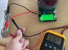
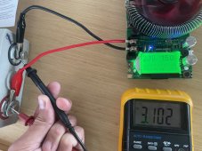
2. Should I perform a capacity test on each individual cell (after fully charging them back up to 3.65v of course). I watched Will's video and it took 5-6 hours for each test. So this would take weeks...
3. How else can I tell if these cells are good? My goal is to try and reinstall only the good cells and form a system comprising only of good ones as long as I have at least 600Ah. I don't want to be in the middle of the ocean and have my batteries go out because my navigational gear and autopilot rely on them, so this is a HUGE safety concern for me.
4. Do you guys think the problem is the batteries at all? It seemed like that to me since they discharged so quickly with such a light 1,000w load on them. 13.4v down to 12.7v was a drastic drop. If not, what else can it be? (The Xantrex Inverter is new, the Solar Controllers are new, and I tightened all the connectors before I disassembled the Lithium cells.) It maybe could be that some of the connectors were so loose they were falling off... It could be that the light rust on the washers was not that good of a connection. But would those problems show voltage dropping like that?
Please help because my life is at stake if this system fails on the open water on a long passage.
Maybe someone can help me please? I suspect that some of my cells are bad. My main goal right now is to test all 48 cells but I'm not sure what is the best way? Wouldn't a capacity test show me a better, more definitive result? (Or does a capacity test on 48 cells take over a month like I was told?)
MY QUESTIONS FOR YOUR GUYS ARE AT THE BOTTOM.... thanks!
SYSTEM SPECS:
- I bought a 2012 Lagoon 450F sailboat boat down in the country of Panama which had a 12v, 1,200Ah LifePo4 system consisting of 48 CALB-brand cells, (3.2v 100Ah cells).
- The batteries are now about 6 years old, and the former owner, who was not an electrician, designed and installed the system himself.
- The original owner connected them first in groups of 4S (4 cells in series), to make twelve, 12v 100Ah batteries. Then he hooked up all twelve batteries in parallel to form a giant 1,200Ah system. Yes, I know that is not how you should connect them.
- Each group of 4s batteries had something called a "QNBBM 4S Lithium Battery Balancer" connecting each group of four. But nothing else.
- There was no BMS!! The previous owner bragged those 4S Lithium Battery Balancers were the BMS...ugh
- There was no Smart Shunt or any kind of way to monitor the system when I bought the boat. He used the Xantrex Inverter/Charger monitor which only displays voltage like a volt meter.
- The system is charged by 2,060W of solar panels, through three Outback Solar Charge Controllers (80A + 80A + 60A).
- The system is also charged through shore power through the Lagoon (Lagoon boat manufacturer) French 220v 60A Cristec battery chargers.
- There was a XANTREX 3,000w FSW3012 Inverter/Charger being used ONLY as an Inverter and not as a charger.
I'm pretty sure some of the batteries are bad but I've been getting bad advice from the "Lithium experts" here in the marina. I want to test these to make sure which ones work.
ORIGINAL PROBLEM:
- The original problem was that the entire system would shut off after turning the inverter on for a few minutes with any kind of load 300w to 1,000w
- The Xantrex 3,000w inverter/charger only had the inverter portion connected, the charger wasn't being used. Instead the shore power connects to the 220v 60A Cristec battery chargers.
- The voltage displayed on the Xantrex Monitor or with a voltmeter directly on the batteries would rapidly go down from 13.4v to about 12.7v to 12.9v and then the Xantrex would shut off. This would happen after only 60-120 seconds of operation. Measuring individual cell voltages on the batteries during this time, I would see it start about 3.4v and watch it go down to about 3.1v before it shut off.
THINGS I'VE FIXED AND NOW KNOW FOR SURE:
- I checked the CALB website and see the chart showing that these batteries drop off completely at around 3.15v for a cell. So they were rapidly discharging down to their lower limit of 12.7v.
- I also know now that LiFePo4 batteries shouldn't show much of a voltage drop, they should hold relatively steady and only drop off at the end when they are empty.
- I know that you need a BMS which is connected to all the batteries and not just the individual cells consisting of each 4S battery. So I think those QNBBM 4S Lithium Battery Balancers were useless.
- I know that batteries need to be first connected in Parallel, and then afterwards, connect them in series to make a 12v system. So eventually I'll be making a 12-cell 3.2v 1,200Ah battery (12P), and then connecting 4 of these together in series (4S), to make a 12P 4S 12v 1,200h system
- I purchased and installed a Victron 500A Smart Shunt, it works great on the temporary Lead Acid batteries I installed
- I purchased a DALY 500A LiFePo4 12v 4S Smart BMS and plan on using that when I put back the Lithium Batteries again. I will also hook them up first as four large 3.2v batteries in Parallel, and then connect those four in series to make them 12v.
- One of the Outback 80A solar controllers was bad, I've since replaced it and luckily they replaced it even though it was 2 months out of warranty. The solar system works great now.
- I found quite a few slightly loose connections, as well as a few connectors that weren't properly crimped on or corroded. When I re-install the system, I purchased a 1/4" thick copper bar to connect the cells to. And some new 1/0 AWG "welding wire" cable with new tinned-copper connectors and professional hydraulic crimper to make my own cables with heat shrinks.
- Also there was a leaky hatch directly above the batteries. The previous owner was an ass and tried to use caulk to stop the leak but that didn't work. The batteries were sitting in over 2" inches of water. (Luckily that was too low to reach the connections). But you could tell that water was dripping on top of them because many battery metal washers had signs of light rust or slight green corrosion. None of it was too bad.
- In the meantime, I needed my 12v lights, fans, refrigerators and freezer to work... so after removing the lithium cells, I was forced to purchase eight 160A Deep Cycle Marine lead acid batteries as a temporary measure until I can work out the problems. If the lithium cells are bad, I'll likely purchase two more of these lead acid batteries and give up with the lithium fix.
ADVICE I WAS GIVEN BY THE "EXPERTS" HERE AT THE MARINA:
- I was told to remove all the cells from the boat, connect all 48 of them in parallel, and place them on a Variable Voltage Charger exactly at 3.65v. I purchased two 10A variable voltage chargers and charged all 48 cells over six days exactly to 3.65v until the chargers displayed 0.0000A.
- To test the them I was told to disconnect all the cells, and record the voltage drop over approximately 2 weeks or whenever they stop dropping voltage, taking readings a few times a day.
- I watched the video by Will Prose showing a capacity tester, so I purchased one of those for $50 and had it shipped here to Panama, but both the "experts" at the Marina here said not to use that capacity tester because it's not needed. They said that the voltage drop readings were all I needed.
- I've been recording voltage levels on each individual cell now for six days. They all started at around 3.64v six days ago, and have been slowly dropping down due to internal resistance each day. Out of the 48 cells and six days of testing, about 12 cells are at around 3.621v, most cells (about 24 of them) are at 3.612v, and the worst 12 of them are at 3.602v
- The Marina "experts" said that these batteries are good. Maybe they are? I still don't trust them because they rapidly discharged before so quickly and I don't think that was from only slightly loose connectors. So I'll continue testing them for another week.
MY QUESTIONS FOR YOUR GUYS:
1. Should I continue testing voltage drop readings on individual cells for another week? The best cells have slowed to only dropping 0.002v a day and the worst cells drop 0.004v a day. The best cell went from 3.64v to 3.621v and the worst cell went from 3.64v to 3.602v. (Not that much difference at all.)
2. Should I perform a capacity test on each individual cell (after fully charging them back up to 3.65v of course). I watched Will's video and it took 5-6 hours for each test. So this would take weeks...
3. How else can I tell if these cells are good? My goal is to try and reinstall only the good cells and form a system comprising only of good ones as long as I have at least 600Ah. I don't want to be in the middle of the ocean and have my batteries go out because my navigational gear and autopilot rely on them, so this is a HUGE safety concern for me.
4. Do you guys think the problem is the batteries at all? It seemed like that to me since they discharged so quickly with such a light 1,000w load on them. 13.4v down to 12.7v was a drastic drop. If not, what else can it be? (The Xantrex Inverter is new, the Solar Controllers are new, and I tightened all the connectors before I disassembled the Lithium cells.) It maybe could be that some of the connectors were so loose they were falling off... It could be that the light rust on the washers was not that good of a connection. But would those problems show voltage dropping like that?
Please help because my life is at stake if this system fails on the open water on a long passage.