diy solar

diy solar

Help understanding ONE string for exterior garage (gable facing due South) Panels on both sides of roof

Someone check this out and verify.
About those Amazon mc4 blocking diode connectors Amazon mc4+blocking diode ; they appear to be rated to 45v.
The mc4 connectors w/blocking diode mc4 connectoper + blocking diode appear rated to only 45v. Did not find that anywhere in the description. It was in the review section Amazon review . Supposedly, this is the 45v diode in the 20 amp Amazon Zookoto mc4 connectors 20sq045 20sq045 diode
If that's the case. Then you need to find one that's rated for your use.
That's just one that I found quickly, for example.
 
If that's the case. Then you need to find one that's rated for your use.
That's just one that I found quickly, for example.
Each of the 16 panels have a current of 8.97A & 37.33V at max power. So, if I'm connecting each side that's in a series (8 panels each on both sides of garage) into its own blocking diode, isn't that 37.33V X 8 = 298.64V and don't the amps stay the same at 8.97A??? Now, after the diode and the Y, when both sides of garage are connected in parallel, (positive to positive and the negative to negative) then it might change, but isn't that ONLY relevant for the wire gauge and inverter specs, since it occurs AFTER the bocking diode? Afterward, (after y) wouldn't the amps be 8.97A X 2 = 17.94A and the volts stay the same at 298.64V? see first image below:

1647264345913.png
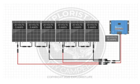
The above diagram shows a six-panel array using 5 Amp, 20 Volt panels wired in a series-parallel configuration of 3-panel series strings wired in parallel (3s2p). First, we need to find the volts and amps of the series wired strings of solar panels. Since solar panels wired in series add their voltages together while the amps stay the same, we add 20V + 20V + 20V. This means that each series string in this series-parallel configuration is 5 Amps at 60 Volts. Since the two 5A – 60V series strings are then wired in parallel, we add the amps while not changing the volts because parallel wired solar panels (or series strings) get their amps added while their volts remain the same. Adding 5A + 5A from the series strings and leaving the volts the same as the series wired strings gives us an array of 10 Amps at 60 Volts.

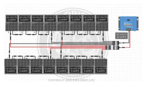
I could try to do something like below to keep the volts and amps down, but I'd have to use more blocking diodes:

1647263531772.png
 
Last edited:
Someone check this out and verify.
About those Amazon mc4 blocking diode connectors Amazon mc4+blocking diode ; they appear to be rated to 45v.
The mc4 connectors w/blocking diode mc4 connectoper + blocking diode appear rated to only 45v. Did not find that anywhere in the description. It was in the review section Amazon review . Supposedly, this is the 45v diode in the 20 amp Amazon Zookoto mc4 connectors 20sq045 20sq045 diode
They have:
Specifications:

Rated Current: 30A
Rated Voltage:1000V DC

So, it appears that this would work fine for me. Am I missing something? Be sure to click 30A after going to link and scroll down to specs:

 
Last edited:
Each of the 16 panels have a current of 8.97A & 37.33V at max power. So, if I'm connecting each side that's in a series (8 panels each on both sides of garage) into its own blocking diode, isn't that 37.33V X 8 = 298.64V and don't the amps stay the same at 8.97A??? Now, after the diode and the Y, when both sides of garage are connected in parallel, (positive to positive and the negative to negative) then it might change, but isn't that ONLY relevant for the wire gauge and inverter specs, since it occurs AFTER the bocking diode?
Yes
 
The only time that I have ever heard of a blocking diode failure, was after a lightning storm.
 
Is there a disadvantage for selecting a higher rated blocking diode than what is needed?
 
What's a good website that I can use to diagram my panel wiring like the images above?
 
Take a look at those linked reviews in post #21, and here is the data sheet for the diode used in the 20amp Zookoto Mouser diode 20sq045 What I question is the max reverse voltage of 45v.
After the Y, amps will be 8.97A X 2 = 17.94A and the volts stay the same at 298.64V. The point of the blocking diode is to stop the DC current from one of the sides of the garage being pulled back into the other side of the garage. So, you are questioning if the Blocking diode can handle enough reverse voltage since its max is 45v and it will blow? Or are you saying that it might let up to 45v past back into the other side and it's too much? And if that blocking diode won't work, what will? Thanks for the reply.
 
Well, I'm finding out that I cannot connect the two sides of the garage in parallel because the amps jump to 8.97A X 2 = 17.94A total for that one string that would run to the inverter. The max input current at the inverter is ONLY 13.5A per string. The 298.64V would be well below the max.

Ok, so AM I ALLOWED TO flirt close with the max input of watts at the inverter based on multiplying the max volts out of each panel that's run in a series? Or do codes typically require you to stay under it by a certain percentage? 335W X 16 panels = 5,360W per string. The inverter allows for a max of 5,700W per string. The max output of current of panels is 8.97, so I can't connect them in parallel. Now what do I do? LOL

  • Number of MPP Trackers: 4
  • Max. Input Power per MPPT [W]: 5700
  • Max. Input Voltage per MPPT [V]: 600
  • Max. Input Current per MPPT [A]: 13.5
As long as you stay below the max voltage. It's perfectly normal to over panel your system.
 
A mini-experiment of what you want to do.
Connect 2 identical panels in parallel. Put one in the sun and cover the other with a blanket.
Measure if any panel conducts current.
Post your findings.
 
Back
Top