diy solar

diy solar

Help w/ Wiring for Victron MPPT, DC-DC Charger, & BMV Shunt

tjoiner1986

New Member
Joined
Jan 10, 2022
Messages
83
Location
Sheffield, AL
Just looking for a 2nd opinion here.

200 watts worth of 12V panels
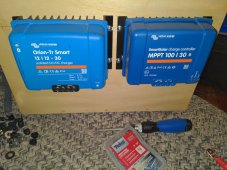
Victron SmartSolar 100/30 charge controller
Orion 12/12-30 isolated DC charger for alternator charging
BMV-712 with shunt for battery monitoring and to remotely disconnect the DC charger during low temps
1200-watt Giandel inverter (may upgrade to a Multiplus down the road if I decide to add shore power)
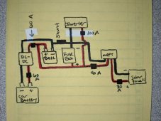
  • 1200W inverter divided by 12V equals 100A breaker, correct?
  • 60A breakers on the charger because that's what the manual calls for.
  • 6 AWG going TO the charger because that's what the manual calls for.
  • Since the charger only outputs no more than 30 amps, I may do 8 AWG (rated 40 A) and a 40 A breaker coming FROM the charger.
  • Per the Victron manual, the BMV shunt goes directly to the battery (-) with the load attached to the other end.
  • 10 AWG between panels and charge controller.
  • 8 AWG between the charge controller and the battery.
  • 4 AWG between the inverter, shunt, batter, everything else.
PXL_20220217_180140912.jpg
 
Last edited:
1200-watt inverter divided by 12 volts equals 100-amp breaker, correct?
No. 1200W / 12V / 0.85 = 118A battery load. 118A x 1.25 = 150A fuse. Choose wire that handles 118A with minimal voltage drop. 2AWG minimum, 1AWG better.

4 AWG between the inverter, shunt, batter, everything else.
1AWG between the batteries, shunt, and inverter based on what I showed above.

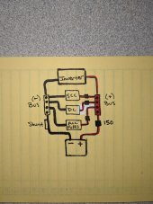
Some comments about your diagram:

Use bus bars to make connecting everything much easier.

battery positive -> main battery fuse -> positive bus bar -> all DC connections
battery negative -> shunt -> negative bus bar -> all DC connections

The "all DC connections" includes the inverter, SCC, DC-DC charger, DC fuse box.
The main battery fuse is the 150A fuse.
You need a fuse between the DC fuse box and the bus bar.
 
No. 1200W / 12V / 0.85 = 118A battery load. 118A x 1.25 = 150A fuse. Choose wire that handles 118A with minimal voltage drop. 2AWG minimum, 1AWG better.


1AWG between the batteries, shunt, and inverter based on what I showed above.

Some comments about your diagram:

Use bus bars to make connecting everything much easier.

battery positive -> main battery fuse -> positive bus bar -> all DC connections
battery negative -> shunt -> negative bus bar -> all DC connections

The "all DC connections" includes the inverter, SCC, DC-DC charger, DC fuse box.
The main battery fuse is the 150A fuse.
You need a fuse between the DC fuse box and the bus bar.

Man... I was way off.

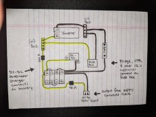
I'm working in a confined space (12.5" x 17" x 11") so routing that 1 or 2 AWG stuff will be tricky but if I'm understanding right, we're basically shooting for this with a breaker/fuse rated for the sum of all the accessories connected to the fuse box?

PXL_20220217_221835186.jpg
 
but if I'm understanding right, we're basically shooting for this with a breaker/fuse rated for the sum of all the accessories connected to the fuse box?
No. You are choosing the battery cable size based on the max current that could be pulled from the batteries at one time. The inverter can pull up to 118A if you are using the full 1200W of the inverter. The DC fuse box loads (lights, water pump, etc.) add to that. Let's say you might have up to 30A of DC loads while maxing out the inverter. And during that time let's say there is no solar and you aren't driving so there's no charge current. So that's 148A possible from the battery. That needs 1AWG. I understand you may never actually max everything out at once but the safest thing to do is to wire and fuse for the max.

In my earlier reply I forgot to add the DC loads to the inverter loads. So with you wiring for 148A and using 1AWG, the main battery fuse should be 185A. Since you can't get a 185A fuse you can use 200A. 1AWG is safe for a 200A fuse.

The fuse between the bus bar and the DC fuse box should be based on just the max DC current you could pull through the fuse box. Pretend you turn on every 12V DC load (lights, pump, charging phone and computer, etc.). How many total watts is that? Wire and fuse the DC fuse box to handle those watts.

Your new diagram looks a lot better. I suggest in real life that you connect the inverter to the bus bar studs closest to the battery connection. Connect the item with the lowest current farthest from the battery connection.
 
OK, so the 100A breaker is heading back to Amazon. A 200A has been ordered.

They didn't have 1 AWG cable, just 2 and 1/0 so I opted for a few feet of 1/0 - figured that should be enough to connect the battery to the bus bars, shunt, and inverter. Also got lugs. Everything should be here Saturday.
 
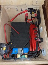
After a lot of work, the diagram below shows how everything is wired at the moment, except for the battery which I do not have installed yet. Because of component changes not expected when I built the wooden box all of this is going in, it's been a challenge getting everything to fit. At the moment, I do not have a breaker between the fuse box and the bus bar, however I believe I can make room for one. I also do not have a breaker between the output of the DC-DC charger and wherever it's going for the same reason (can't find room for it) but I think I can find a spot.

Because the charge controller and alternator charger are sources of power and not loads, would it make more sense for those items to be connected directly to the battery/BMS rather than the bus bars?

PXL_20220226_162944949.jpg

PXL_20220226_161443543.jpg
 
Because the charge controller and alternator charger are sources of power and not loads, would it make more sense for those items to be connected directly to the battery/BMS rather than the bus bars?
Nope. Connect them to the bus bars. Only the shunt should be connected to the battery negative. And only the main battery fuse should be connected to the battery positive.

If you connect anything else directly to the battery then the shunt will never be able to give you an accurate SOC reading.
 
One word of warning about your installation of your Victron SCC. The following is from the the Installation chapter of manual:

Mount vertically on a non-flammable surface, with the power terminals facing downwards. Observe a minimum clearance of 10 cm under and above the product for optimal cooling.

You currently have the SCC upside down. I know it makes it a giant PITA to have the wire connections on the bottom when you mount the SCC so close to the bottom of the box (my setup is similar). I don't know why it can't be upside down but the manual makes it clear that you can't.

Please be sure to read the entire Installation chapter and the preceding Safety Instructions chapter.
 
I just noticed a serious problem with your negative bus bar. This may be temporary while you work on it but just incase: It is critical that the washers and nuts of the bus bar studs are used to ensure the wire lugs are held tight against the bus bar. In the your picture the 2nd lug from the bottom (as seen in the picture) you have the split washer between the bus bar and the wire lug. That's dangerous. It should always be bus bar - wire lug - flat washer - split washer - nut.
 
The chargers and inverter will get hot in use and need to disipate excess heat. Units need to be mounted vertically provision for good airflow , the shunt mounted directly above the Orion b2b is blocking air flow, and will not be too happy getting hot, as will the cells.The comments about upside down are due to confusing the mppt with the Orion. Not critical with the Orion .
I guess the battery is intended to be in the box also.
The amazon low cost breakers are not very reliable, replace with fuses or Bluesea/Bussman breakers.
You really need to rethink about heat buildup in the small space. I suggest using computer fans and ventilation or a rethink and distributing parts around the vehicle.

The concept of overcurrent protection needs the fuse or breaker as close as practical to the power source, the battery. This protects the cable and whatever is on the end of the cable. I recommend a 'master fuse' directly at battery, a MRBF fuse in a Bluesea holder is just about OK for a 12v lithium battery, ideally a classT would be fitted

Mike
Hmmm... I could possibly relocate the Orion outside the box. Under the dash beside the pedals perhaps. And then put an exhaust fan in its place. I don't really like the Orion being in here anyway. Takes up too much space.

Edit: Orion removed. May simply mount it to the outside of the box. The MPPT is currently mounted to a cabinet next to this box. I may also relocate it to the outside of this box beside the Orion.

PXL_20220226_212035029.jpg
 
Last edited:
Oops. The Orion looks just like my SmartSolar MPPT.

They ARE nearly identical. Same width and height but the Orion has a larger heatsink that makes it taller (depth) than the SmartSolar. Also, the Orion is a lighter blue.

The new layout:
16459154211957685902905629873530.jpg
 
Last edited:
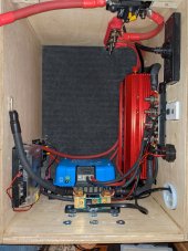
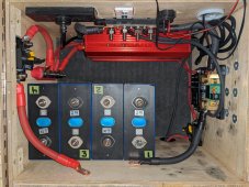
I believe I'm slowly getting there. Moving the Orion to the outside really allowed for more flexibility.

There's now a 2" cable port in the side to pass through the output from the Orion and MPPT.

1/0 AWG was used between the battery, bus bars, shunt, and inverter while 8 AWG was used between the fuse box and MPPT. 6 AWG will be used with the Orion.

The fuse box (12V fridge, USB ports) is now under the shunt.

The breakers for the Orion (60A) and MPPT (40A) output are beside the fuse box and shunt but I may move these around the corner to beside the battery. This will allow me to install a couple PC fans in the future.

There will be a 40A breaker for the fuse box next to the positive bus bar. I'll never get close to drawing 40 amps (probably 15A max) but that's what the cable is rated for.

The plan is for the BMS to go on top of the battery but that might change (side or end of the battery?) once it arrives and I get a better idea of its size and layout.

PXL_20220227_224016216.jpg
 
I just noticed a serious problem with your negative bus bar. This may be temporary while you work on it but just incase: It is critical that the washers and nuts of the bus bar studs are used to ensure the wire lugs are held tight against the bus bar. In the your picture the 2nd lug from the bottom (as seen in the picture) you have the split washer between the bus bar and the wire lug. That's dangerous. It should always be bus bar - wire lug - flat washer - split washer - nut.
Seconded. I once accidentally put a split washer against my bus bar under my battery lead. It got welded to the lug and the bus bar due to small contact surfaces.
 
Back
Top