diy solar

diy solar

Help with 24V system wire size

Taytus

New Member
Joined
Mar 30, 2021
Messages
11
Hello everyone, I'm brand new to all this so excuse my silly questions :)

I will have a 3000W 24V Inverter so that means I will have to wire my small cabin with a wire that supports125 AMP?

Am I doing this calculation correctly?

What cable size that would be? What is your recommendation?

Thank you so so much for all your help.
 
3000W / 24V is 125A. But many people throw in an inefficiency factor and divide that by 0.85 which suggests you should wire for 150A. Using the Blue Sea Systems wire size chart (which assumes you are using high quality stranded copper wire with 105ºC insulation) you would want to use 1AWG. This also assumes the round trip wire length to/from your inverter is under 15 feet. And you will want a fuse sized from 175A-200A.
 
For the ac side the wire and breaker is based on the load.
If this is an RV the master breaker is typically 30 amps which means 10 awg triplex wire.

For the dc side...
3000 ac watts / .85 conversion factor / 24 volts low cutoff = 147.058823529 service amps
147.058823529 service amps / .8 fuse headroom = 183.823529412 fault amps.

That means minimum 2 awg pure copper wire with insulation rated for 105C and a 200 amp fuse.
 
Thank you so much @rmaddy and @smoothJoey. My question wasn't clear enough (I was asking for the AC side), but you guys have been incredibly helpful and answered what I needed to know.

Much appreciated.
 
Thank you so much @rmaddy and @smoothJoey. My question wasn't clear enough (I was asking for the AC side), but you guys have been incredibly helpful and answered what I needed to know.

Much appreciated.
So it is an RV?

UPDATE: I see that it is a cabin.

q: Will you be doing proper stuctured wiring with an ac distribution panel?
 
@smoothJoey I don't know yet. I might. I'm still learning but I would like to have the cabin all wired up but I don't have large loads (yet)

Should I? When is a distribution panel required or recommended?

Edit: The cabin is about 1000 sq.ft.
 
@smoothJoey I don't know yet. I might. I'm still learning but I would like to have the cabin all wired up but I don't have large loads (yet)

Should I? When is a distribution panel required or recommended?

Edit: The cabin is about 1000 sq.ft.

The way I see it there are only 2 levels of wiring.
1. Use an extension cord + power bar(hopefully with a breaker built in) plugged into the outlets on the inverter.
2. Hardwire a 10 awg wire to a distribution center.
That way gives you a feeder with master breaker and branch circuits with corresponding breakers.

1. Is easy but limiting.
2. Requires a bit of learning, especially the grounding part.
I'll warn you right now that "grounding" is actually multiple but related concepts.
Luckily @FilterGuy wrote up some good doco on the subject.
 
Hello everyone, I'm brand new to all this so excuse my silly questions :)

I will have a 3000W 24V Inverter so that means I will have to wire my small cabin with a wire that supports125 AMP?

Am I doing this calculation correctly?

What cable size that would be? What is your recommendation?

Thank you so so much for all your help.
Your 3kW inverter cannot put out more than 25Amps of AC current (assuming it’s a 120VAC inverter).

That should be wired using suitably sized wire (probably 6AWG unless you need to worry about derating for high ambient temps) to your mains panel.

The rest of the wiring depends on the circuit/breaker size (14AWG for 15A circuits / 12AWG for 20A circuits).

The DC wiring between your battery and your inverter. It will be carrying up to 125A and needs wiring rated for 195A (so possibly as little as 1AWG if the wire run is short and through air (no conduit) but the safer thing to do would be to use 2/0 welder’s cable…
 
How did you calculate the need for 195A wiring?
I figured a full 3kW supplier from a 24V battery translates to 125A.

To avoid nuisance trips, you probably want your breaker sized at ~125% that level or ~150A.

Sizing the wire 125% of the breaker size takes you to 188A (or 195A from a full 156A breaker).

That is conservative but for me, at least, the one place there is little upside to pushing the limits is the highest-current path from battery to inverter.

The battery will rarely if ever be down at 24V (at least if LiFePO4 - he did not specify which battery chemistry he has) so if we take a minimum voltage of 25.6V instead, that would bring max current down to 117A (or 183A after the two corrections) but that reminds me that I overlooked inverter efficiency (which works in the opposite direction).

My 24V 3kW inverter (WZRELB) has efficiency of 90%, so 3000W out needs 3333W in or 130A @ 25.6V.

So my earlier estimate was not as conservative as I thought and planning for 130A of sustained current, protected by a 160A fuse and wire sized for a full 200A (or even 205A) would be safer.

Would you see it differently?
 
I'd say @fafrd is being a little conservative, but there's nothing wrong with that.

Besides, people often size the wire for the ampacity it will carry, and realize later that the losses on the wire is killing time. The OP didn't actually say what distance his DC has to go. Bigger wire is expensive, but often worth it.

Of course, since he was asking a question about the AC side, we are all just talking to ourselves. o_O
 
Some of those are good answers, aren't they? Even if I am running nowhere near 1AWG, or even 2AWG, on the DC side of my setup. Well, I only have a 2000W inverter connected so far, so maybe I will get away with it. Actually I am getting away with it, in testing.

On the AC side, well, I'm currently using a power strip which I happened to have lying around, which might be 16AWG, with a 700W microwave and a 1000W electric kettle as the primary power consumers. I admit I take care not to run them at the same time, and they don't run for more than a few minutes at a time. One of these days, after I add more than 75AH@24V, I might hook up the 1500W modified sine wave inverter and try running the electric kettle, and the microwave, at the same time. But the way my minivan is situated, there won't be any long runs on the DC side, partly because that's the way I prefer things. On the AC side, well, I guess there will be two sets of plugs, one for MSW and one for true sine wave. So I guess I wouldn't go heavy on the copper with either of those.

Oh. I found this: https://www.usawire-cable.com/pdfs/nec ampacities.pdf
 
I'd say @fafrd is being a little conservative, but there's nothing wrong with that.

Besides, people often size the wire for the ampacity it will carry, and realize later that the losses on the wire is killing time. The OP didn't actually say what distance his DC has to go. Bigger wire is expensive, but often worth it.

Of course, since he was asking a question about the AC side, we are all just talking to ourselves. o_O
Absolutely correct (though since he stated he was a noob, no harm in giving him a list of other considerations to keep in mind).

The fact you guys apparently consider my calculations on the conservative side is reassuring.

I’m using 2/0 Welder’s wire to feed 2 1kW GTIL inverters from my 24V LiFePO4 battery now (with separate runs to reduce voltage drop) protected by a 225A MEBF fuse.

No safety concerns at all, but I want to wire in my 3KW PSW inverter to be used only during a power outage and have been thinking about how much risk I’d be taking by just extending a single pair of 2/0 cables.

My 3KW inverter has 90% efficiency and will be drawing 130.2A off of my battery if I let it run flat out (so fuse will not blow even at max load).

2/0AWG is rated for 283A when used for ‘Chassis Wiring’ so tons of headroom as long as my through-air wiring qualifies.

But 2/0AWG is only rated for 190A when used for ‘Power Transmission’ which generally means wired through conduit but also means continuous use (as should probably apply to an inverter).

My inverter should never draw over 130A but if it shorts and draws over 190A but under 225, that’s the potential risk I may be taking.

I suppose another 150A fuse connected between the extended cable and the 3kW PSW inverter would be an easy way to eliminate that small remaining risk but if all of you think chassis wiring limits apply even to DC wires feeding inverters for continuous use, I may not bother…
 
Some of those are good answers, aren't they? Even if I am running nowhere near 1AWG, or even 2AWG, on the DC side of my setup. Well, I only have a 2000W inverter connected so far, so maybe I will get away with it. Actually I am getting away with it, in testing.

On the AC side, well, I'm currently using a power strip which I happened to have lying around, which might be 16AWG, with a 700W microwave and a 1000W electric kettle as the primary power consumers. I admit I take care not to run them at the same time, and they don't run for more than a few minutes at a time. One of these days, after I add more than 75AH@24V, I might hook up the 1500W modified sine wave inverter and try running the electric kettle, and the microwave, at the same time. But the way my minivan is situated, there won't be any long runs on the DC side, partly because that's the way I prefer things. On the AC side, well, I guess there will be two sets of plugs, one for MSW and one for true sine wave. So I guess I wouldn't go heavy on the copper with either of those.

Oh. I found this: https://www.usawire-cable.com/pdfs/nec ampacities.pdf
That’s fine for AC wiring, but this is better when you have DC wires running in conduit (power distribution) or through air (chassis wiring): https://www.powerstream.com/Wire_Size.htm

Also, don’t forget to check the derating you should apply based on max ambient temps the wires will be used in…
 
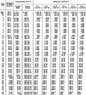
That is for the ampacity, which is only half of what drives the size of your wire. The other is the loss on the wire due to resistance. For that you need to look at a different NEC table. I don't remember for sure, but I thought it was NEC chapter 4 table 8 (but who knows?). Here's a pic of it:
awg-ohms-per-1000-feet.jpg
So let's say you have your batteries 40 feet from your inverter, and you expect a maximum current of 100A (40 feet is extreme, but stay with me). Based on the ampacity, you decide 4AWG should be close enough (Ampacity of 95A with 90°C rated insulation). Now if you look at the table above, you see that 4AWG has a nominal resistance (at 25°C) of about 0.2533 ohms per thousand feet. In 40 ft, the resistance is 40 * 0.2533 / 1000 = 0.010132 ohms. Now multiply that resistance times the current of 100A, and you get a loss in 40 ft of 40*0.010132 = 0.405V. But wait! You have current going down two wires (red and black) for that 40 feet. So the total loss is actually 2 * 0.405V = 0.81V. In a 12V system, loosing 0.81V in the wire is a killer. It's only a little better in a 24V system.
 
That is for the ampacity, which is only half of what drives the size of your wire. The other is the loss on the wire due to resistance. For that you need to look at a different NEC table. I don't remember for sure, but I thought it was NEC chapter 4 table 8 (but who knows?). Here's a pic of it:
View attachment 67495
So let's say you have your batteries 40 feet from your inverter, and you expect a maximum current of 100A (40 feet is extreme, but stay with me). Based on the ampacity, you decide 4AWG should be close enough (Ampacity of 95A with 90°C rated insulation). Now if you look at the table above, you see that 4AWG has a nominal resistance (at 25°C) of about 0.2533 ohms per thousand feet. In 40 ft, the resistance is 40 * 0.2533 / 1000 = 0.010132 ohms. Now multiply that resistance times the current of 100A, and you get a loss in 40 ft of 40*0.010132 = 0.405V. But wait! You have current going down two wires (red and black) for that 40 feet. So the total loss is actually 2 * 0.405V = 0.81V. In a 12V system, loosing 0.81V in the wire is a killer. It's only a little better in a 24V system.
Correct. You should generally aim to keep voltage losses under 3% (and certainly under 5%).
 
I figured a full 3kW supplier from a 24V battery translates to 125A.

To avoid nuisance trips, you probably want your breaker sized at ~125% that level or ~150A.

Sizing the wire 125% of the breaker size takes you to 188A (or 195A from a full 156A breaker).

That is conservative but for me, at least, the one place there is little upside to pushing the limits is the highest-current path from battery to inverter.

The battery will rarely if ever be down at 24V (at least if LiFePO4 - he did not specify which battery chemistry he has) so if we take a minimum voltage of 25.6V instead, that would bring max current down to 117A (or 183A after the two corrections) but that reminds me that I overlooked inverter efficiency (which works in the opposite direction).

My 24V 3kW inverter (WZRELB) has efficiency of 90%, so 3000W out needs 3333W in or 130A @ 25.6V.

So my earlier estimate was not as conservative as I thought and planning for 130A of sustained current, protected by a 160A fuse and wire sized for a full 200A (or even 205A) would be safer.

Would you see it differently?
I generally don't add the 2nd 125% kicker over the breaker size.
 
I generally don't add the 2nd 125% kicker over the breaker size.
Gotcha - thanks. That ‘kicker’ (or safety margin) is required for DC PV wires and for DC power distribution from batteries, I actually consider that 25% margin more important than the 25% margin Ethernet actual peak current and breaker size (which is only a convenience factor and not a safety issue - ie: reduced nuisance trips).

For an application like this, would you use ‘Chasis Wiring’ limits or ‘Power Distribution’ limits??
 
Back
Top