diy solar

diy solar

Help with a revised system design for a 35 ft boat

danphillips

New Member
Joined
Oct 29, 2019
Messages
108
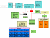
Hoping someone can review and point out any weaknesses in this design for my boat refit.
I am keeping the starting system separate from the house batteries. At some time in the future I may add a B2B charger if it's needed.

Looking to be able to discharge up to 2000 watts - most loads will be well below this. Wanting a simple configuration and will disconnect solar and house batteries when stored for extended periods of time.

I already own the inverter / charger and 12 Calb 180ah batteries. I'm looking to order the Victron MPPT Smart Solar 150/6a SCC and Chargery BMS.
Not sure what contractors should be used so any help is welcome.
1594396862597.png
 

Attachments

  • Boat Electrical.pdf
    99 KB · Views: 13
Can someone with experience help me here please. I need to order supplies early next week. Thanks
 
I have a 41’ Sailboat, I am very interested in following this thread. Sorry I’m no help to you, I am a complete neophyte to this type of thing
 
@Capt_Chris , if you want to brainstorm some ideas let me know. My main concern is to keep it simple and be able to go into power down while at dock
 
Not familiar with the chargery and not a hardware guy, but wouldn't you just want a DC contactor for 2000W, 12V DC, > 167 amps that is "normally open"? (double check what the chargery manual says about it being NC vs NO).

Why a contactor though? They'd be bigger and more expensive compared to an automotive relay. The coils don't pull much, typically under a couple of watts.
 
Last edited:
From my research an automotive relay is not rated for continuous duty. As for the chargery bms they have separate controls for charge and discharge disconnect
 
There are several threads about what relays to use with the Chargery. The search engine is your friend. When designing, it is best .... in my opinion .... to be able to switch load and charge via the low current side ... or power switch .... or remote control input instead of switching the higher current DC side.
 
@Bob B , I am new to all this, If I understand your advice, it is best to cut off the charge / discharge instead of controlling the 120v ac side. Is this correct ?
 
@danphillips Some devices have the capability of being enabled and disabled via a dry contact .... this would be very low current switching .... or there may be a power switch on some inverters and a relay contact could be put in series with the switch to turn it on and off.
What I am saying is I prefer to find a way to shut off the charge or load with the least amount of current switching possible. That way lower power SSR relays can be used instead of high powered contactors.
 
@Bob B , from what I understand, the Inverter / Charger and the SCC should handle the charge and discharge limits. The BMS is to protect the High and Low voltage in the event either the SCC or the Inverter do not do their job as designed\
 
@Bob B , from what I understand, the Inverter / Charger and the SCC should handle the charge and discharge limits. The BMS is to protect the High and Low voltage in the event either the SCC or the Inverter do not do their job as designed\

That has nothing to do with what I am saying .... I am just saying that I prefer to have the BMS relays located somewhere besides in the main DC circuit .... That way you don't need to be passing all the current thru those relays all the time.
 
Back
Top